Stef,
if someone had the knowledge, he would describe how complex signals, which have no repetition and have 40 dB difference between a carrier signal and small signal overtones, can be transmitted and especially measured in this form (to my knowledge, this problem is addressed for the first time by Siegfried Linkwitz and has not been technically solved until today).
That such a signal is heard and evaluated by humans, I have already learned in my studies, these are old pychoacoustic basics.
In contrast to this is the fact that in the analysis usually steady states of tones are examined. This is a rarely occurring special case, which can be used as an approximation for simplification.
The issue here is the quality of the oscillating system, since, according to F.E. Toole, humans hear sound fronts and not "tones" from about 1 kHz. This results in the fact that the acoustic phase has a very high importance, but also how exactly the system vibrates, i.e. whether it has a Q below 0.5 (it is overdamped and does not fully resonate) or above 0.5 (it is underdamped and resonates). This issue should be understood in the context that the loudspeaker is not simply a signal receiver and always has feedback effects on the amplifier. These effects can be simulated and that is where very low resistances in the milli ohm range are effective. Otherwise, why would you use silver-plated cables?
Another issue:
The new Q17 circuit with jfet after the opamp requires lowering the relative error tolerance in the simulation to get results closer to reality. Even with these simulations, it is not fundamentally trivial to simulate complex signals and especially to evaluate them accurately.
Therefore, I do not find the attempt reprehensible to test in practice.
But to your point:
I also believed all this many years and very many experiments ago, but at that time I also did not have the technical possibilities, construction materials and comparison possibilities.
Tim
Stef,
If you want to reduce the chances of "connection errors" don't from Aliexpress. Those connectors are clones of Molex, Phoenix, TE Conn, Etc... and are made from inferior materials. Plastic housings that melt easily when soldering headers to pcb boards, metal crimps that do not hold tension because they are thinner than genuine brands. I know the price is tempting but they are junk and WILL fail over time.
If you want to reduce the chances of "connection errors" don't from Aliexpress. Those connectors are clones of Molex, Phoenix, TE Conn, Etc... and are made from inferior materials. Plastic housings that melt easily when soldering headers to pcb boards, metal crimps that do not hold tension because they are thinner than genuine brands. I know the price is tempting but they are junk and WILL fail over time.

Hello,
This is what happened with the current connectors. I took them apart from a old prototype and the plastic melted without me seeing it. However, I desolder super quickly. 😉
If you can find me the references to the originals on Mouser, I would. I did not find them. Too many models that look the same and the docs aren't very informative.
In the Turbo BOM, I put a PHOENIX parts connector but with a simple screw.
In the next version I add the Fastons anyway. A classic that never lets you down.
Stef.
Good morning,
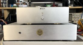
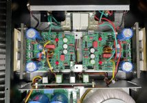
Here I describe to you the tests I did last night with the Q17-Turbo 1.2, the Q17-Mini 1.3 and the Burmester 956 clone and the impressions I got from them. I broke down, I couldn't wait any longer for the comparisons.
First test: The Q17-Turbo compared to the Q17-Mini 1.3 on a pair of Triangle Titus in close range listening at average sound level.
The Q17-Mini is equipped with a single classic power supply with Vishay bridges and a 160VA transformer.
The Q17-Turbo is equipped with the same single power supply but with a 400VA transformer.
Both amps are equipped with the same FQA/FQP power transistors.
The sound level is the same on both amps (same slider position on the volume control).
The Q17-Turbo has a higher level of detail and a wider stereo image. It also seems more dynamic. The bass level is comparable. The voice timbres are quite identical. No sonic aggression. Without a signal, the Q17-Mini is super quiet. The Turbo has a hum that is always present. Light but present.
Knowing that the Q17-Mini is in position R32=0R while the Q17-Turbo is with R32=10R and in addition a filter on the GND for connection to the ground / chassis. Without that, it's hum.
Second test: The Q17-Turbo and the Burmester 956 compared on a pair of Dynaudio Contour 3.4s.
Listening is done at a louder volume than with the small Triangle speakers.
The preamp is a Topping D30 Pro connected to a Raspberry with Volumio. The Burmester is connected via XLR and the Q17-Turbo via RCA. To have the same volume, I must be on 31 with the Burmester and 26 with the Q17-Turbo (by ear, I did not measure).
Same problem as with the Triangle. I hear a very slight hum with the Q17-Turbo (ear glued to the edge of the HP tweeter) and nothing with the Burmester.
In terms of sound, the Q17-Turbo rises to the same level as the Burmester. He controls the bass correctly. The bass drag is almost identical to the Burmester. The Burmester remains a little more dynamic and dry on the bass (it has a very high dumping factor).
The stereo image is a little wider with the Q17-Turbo. The stereo midpoint is better centered with the Q17-Turbo. I have a slight shift to the left with the Burmester. It could also be the opposite, a slight new shift on the Q17 but I didn't hear it with the Triangle.
The voice timbres are quite similar but a little softer with the Q17-Turbo. No excess grain on the voices.
To sum up. Progress in the quality of the sound produced by the new Q17.3 circuit compared to the original circuit but a sensitivity to hum which must be corrected. Knowing that you have to find where it comes from (from the PCB or the circuit itself). I don't think it's the wiring. To do this, I will mount the two Q17-Mini 2.0 cards that I built in the Q17-Mini 1.3 box. I would therefore have exactly the same configuration (box, cabling, power supply, etc.). This should allow me to better analyze the behavior of the new circuit.
In terms of reliability, the new board seems ok. The amp ran for 4 days continuously with music without any problems. Nothing in the box exceeds 45°C.
Best Regards,
Stef.
Attachments
Last edited:
Hello,
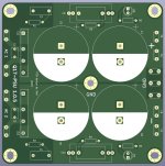
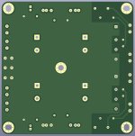
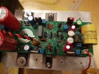
I have uploaded a new version 1.0.5 of the Q17-PSU power supply. I optimized the ground planes and tracks to minimize interference between the AC and DC part of the PCB.
https://github.com/stefaweb/Q17-Amplifier/tree/main/Q17-PSU-1.0.5
Stef.
I have uploaded a new version 1.0.5 of the Q17-PSU power supply. I optimized the ground planes and tracks to minimize interference between the AC and DC part of the PCB.
https://github.com/stefaweb/Q17-Amplifier/tree/main/Q17-PSU-1.0.5
Stef.
Attachments
Supplement on the power supply PCB 1.0.4 and below.
If you made them, don't use them. They don't work (they produce hum). There is a 95% chance that the hum problem with the Turbo comes from there.
In a week I should have new PCB and I will know.
Stef.
If you made them, don't use them. They don't work (they produce hum). There is a 95% chance that the hum problem with the Turbo comes from there.
In a week I should have new PCB and I will know.
Stef.
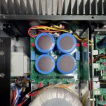
Hello,
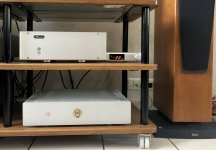
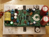
I stole the Chinese orange power supply from the Mini 1.3 box and I installed it in the Turbo.
The Q17-Turbo no longer hums. It was the power supply that was messing up. R32=0R with Triangle Titus (90 dB/W/m): Very very very light hum. Nothing with R32=10R. We should hear nothing on the Dynaudio even with R32=0R.
A story with a happy ending.
I will keep you posted for the new PSU PCB.
Stef.
Hello,
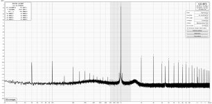
I put the boxed Turbo back in REW. It's a little worse than the card alone in "labs configuration" but the Q17 in the real world has nothing to be ashamed of.
Very nice amp new amp. It makes these very brilliant Triangle Titus speakers listenable for more than an hour without grinding your teeth. I rediscovered them while they had been sleeping on top of a cupboard for years.
Stef.
Attachments
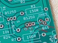
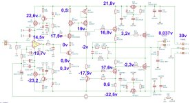
-- Q17.2 single output version of Tiberius
G and D pins of BS250 (Q11) is shorted on pcb.
.... and 2 pin (collector, base) of KSA992 (Q10) is also shorted on pcb.
Is it right?
Do these C3, C6 have polarity?
G and D pins of BS250 (Q11) is shorted on pcb.
.... and 2 pin (collector, base) of KSA992 (Q10) is also shorted on pcb.
Is it right?
Do these C3, C6 have polarity?
Attachments
Last edited:
Hello,
The problem of hum with the PSU is solved with the latest version.
The Q17-PSU 1.0.5 Gerber files are available on the Github repository.
https://github.com/stefaweb/Q17-Amplifier/tree/main/Q17-PSU-1.0.5
Have fun.
Stef.
The problem of hum with the PSU is solved with the latest version.
The Q17-PSU 1.0.5 Gerber files are available on the Github repository.
https://github.com/stefaweb/Q17-Amplifier/tree/main/Q17-PSU-1.0.5
Have fun.
Stef.
Attachments
Hello,
I have finished testing v2.0 of the Q17-Mini. I installed them instead of the 1.3 boards in my amp. It works perfectly.
The version published on the Github repository can now be used without problem. I didn't even have to make any last minute changes to the PCB.
Have fun!
Stef.
I have finished testing v2.0 of the Q17-Mini. I installed them instead of the 1.3 boards in my amp. It works perfectly.
The version published on the Github repository can now be used without problem. I didn't even have to make any last minute changes to the PCB.
Have fun!
Stef.
Attachments
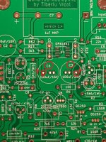
I built Q17 (17.2 version, one pair output) of Tiberius with the shared mouser project.
Power supply is +/-50VDC with no load.
I used DIP8-SOP8 adapter for opamp rolling. https://ko.aliexpress.com/item/4000036521132.html
I used LT1122 instead of OPA1641. I'm waiting SOIC8-DIP8 adapter for using OPA1641.
I powered it up and there were no smoke or burning stuff.
I checked dc offset without any load using voltmeter at speaker binding posts directly
.. but it has shown around negative 9V (not mV).
It seems that it's not working properly.
What can I do to solve this problem?
Attachments

Hello,
Check Q12.
Use 1A fuses on DC power when power up the board for the first time.
Regards,
Stef.
Check Q12.
Use 1A fuses on DC power when power up the board for the first time.
Regards,
Stef.
Is your plan to use an SOIC8 to DIP8 opamp adapter with DIP8 socket then another DIP8 back to SOIC8 adapter stacked on top of that? That is not a good idea IMO. Just solder the proper package SOIC8 opamp directly on the board, OPA1641 or OPA1611.
After the lt Spice simulation, the lt1122 does not work.I built Q17 (17.2 version, one pair output) of Tiberius with the shared mouser project.
Power supply is +/-50VDC with no load.
I used DIP8-SOP8 adapter for opamp rolling. https://ko.aliexpress.com/item/4000036521132.html
I used LT1122 instead of OPA1641. I'm waiting SOIC8-DIP8 adapter for using OPA1641.
@Tim1999de @Vunce
Thank you for reply.
The opamp LT1122 is so hot.
I can not touch it for one sec.
I will try it again with OPA1641 with adapter.
Thank you for reply.
The opamp LT1122 is so hot.
I can not touch it for one sec.
I will try it again with OPA1641 with adapter.
Last edited:
I tried it again with OPA1611.
It showed dc offset around -4.5V.
At first try with OPA1611, red LEDs did not turn on.
Then I reflow OPA1611 with adapter and tried again.
It seems that there is no any burnt resistor.
I don't know how I proceed.
It showed dc offset around -4.5V.
At first try with OPA1611, red LEDs did not turn on.
Then I reflow OPA1611 with adapter and tried again.
It seems that there is no any burnt resistor.
I don't know how I proceed.
Attachments

Last edited:
- Home
- Amplifiers
- Solid State
- Q17 - an audiophile approach to perfect sound