Ok fair!Sure, if present and working, but I've changed an awful lot of 405 power transistors.
My reasoning is if quad make amps work in this way to be able to drive the esl’s with a margin of safety why are we not looking to include this in the mod. Surely many 405-2 mod’rs looking for the best will have what is questionably one of the best affordable speakers sh (ESL63’s) to listen to the best version of this amp.
It’s a bit like saying let’s rebuild a mustang into a Shelby but not upgrade the breaks cos we only ever want to drive fast, not stop. And if we crash we can repair the damage after! !
I could build external relay protection, but it isn’t the same as effective current limiting. Perhaps help identifying the required circuitry and how to include this effectively would appeal to some builders as an option?
I agree completely. Any 405 or 405-2 without SOA control isn't really a 405 at all. Not many power amps are built without SOA protection.


Hi Tibi
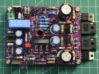
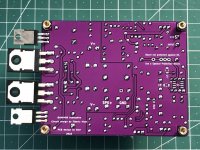
Finally my two Q17 are finished, well I need some additional mechanical work, but the electronic is working.
A lot of trials and tribulations though, but nothing to blame the Q17 or you.
First the substitutes for 2sc2240/2sa970 had different pinouts. I know you said that should be checked , but I forgot. I always use a vario transformer to slowly start up new circuits, so no smoke...
I had some original 2sc/2sa that I used instead. Still the amp didn´t work. After a lot of measurements and head scratching, I came to the conclusion, that the BS250 didn´t work properly.
Mouser did not have BS250 so I sourced them from another supplier. A Chinese source. I shouldn´t have done that! It turned out that the BS250 they sent me was not MOSfets but bipolar npn transistors!!!
I was fortunate enough to find some BS250 in a Danish supplier and now the amp finally worked.
I finished the other channel and gave them a listen. Very promising indeed! I use a DSC 2.0 with potato chips and reclocker and with lifepo4 batteries as PS. Suddenly one of the lifepo4 ran out of charge and the DSC 2.0 went into a stage where it sent out full level digital noise!. That killed the two Q 17 ;-(
Now finally I changed all the defective parts and the amps are working again. I changed the PS for the DSC 2.0 to a traditional(but high quality) PS and it performs actually even better now.
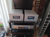
I must congratulate you with your work on this amp. They are truly great! On an overall basis the best I have made! And I have made many:
Almost all of the PASS designs
FetZilla
Fet circlotron
RMI-FC1000 single stage amp by Roender
A Goldmund Telos 350 clone (a powerhouse and still delicate. Beats the Q17 in sheer power and is very good sounding )
My_ref Fremer edition (at first I thought this was great, but in the long run boring an artificial)
An OTL with 6C33 tubes (a near clone of the Novacron from Atmasphere) 2X60 Watt out , but uses 700W constantly to produce that. . The OTL is not a traditional sounding tube amp, because of the missing transformers. It has powerful and precise bass and is very transparent.
And a lot of others, that I don´t recall right now
The OTL has been my preferred amp for quite a while, but Q17 will replace it now.
The thing is that the Q17 has all the best from Goldmund and the OTL. It has the same way to make the instruments sound real as the OTL and it has the crispness and HF extension of the Goldmund and NEVER sounds harsh. Bravo! And thanks. Now I can listen to music without being in a sauna. And I don´t have to wait half an hour before the sound is great!
Finally my two Q17 are finished, well I need some additional mechanical work, but the electronic is working.
A lot of trials and tribulations though, but nothing to blame the Q17 or you.
First the substitutes for 2sc2240/2sa970 had different pinouts. I know you said that should be checked , but I forgot. I always use a vario transformer to slowly start up new circuits, so no smoke...
I had some original 2sc/2sa that I used instead. Still the amp didn´t work. After a lot of measurements and head scratching, I came to the conclusion, that the BS250 didn´t work properly.
Mouser did not have BS250 so I sourced them from another supplier. A Chinese source. I shouldn´t have done that! It turned out that the BS250 they sent me was not MOSfets but bipolar npn transistors!!!
I was fortunate enough to find some BS250 in a Danish supplier and now the amp finally worked.
I finished the other channel and gave them a listen. Very promising indeed! I use a DSC 2.0 with potato chips and reclocker and with lifepo4 batteries as PS. Suddenly one of the lifepo4 ran out of charge and the DSC 2.0 went into a stage where it sent out full level digital noise!. That killed the two Q 17 ;-(
Now finally I changed all the defective parts and the amps are working again. I changed the PS for the DSC 2.0 to a traditional(but high quality) PS and it performs actually even better now.
I must congratulate you with your work on this amp. They are truly great! On an overall basis the best I have made! And I have made many:
Almost all of the PASS designs
FetZilla
Fet circlotron
RMI-FC1000 single stage amp by Roender
A Goldmund Telos 350 clone (a powerhouse and still delicate. Beats the Q17 in sheer power and is very good sounding )
My_ref Fremer edition (at first I thought this was great, but in the long run boring an artificial)
An OTL with 6C33 tubes (a near clone of the Novacron from Atmasphere) 2X60 Watt out , but uses 700W constantly to produce that. . The OTL is not a traditional sounding tube amp, because of the missing transformers. It has powerful and precise bass and is very transparent.
And a lot of others, that I don´t recall right now
The OTL has been my preferred amp for quite a while, but Q17 will replace it now.
The thing is that the Q17 has all the best from Goldmund and the OTL. It has the same way to make the instruments sound real as the OTL and it has the crispness and HF extension of the Goldmund and NEVER sounds harsh. Bravo! And thanks. Now I can listen to music without being in a sauna. And I don´t have to wait half an hour before the sound is great!
Attachments
One thing that puzzles me about this thread after I read through it all just now:
I can understand why some wants to change the design, as it is an open source project, and it is hard to overcome the itch of changing something.
But why so few people just tried the Tibi version first and commented on that is very strange.
The amp is easy to build , completely stable and quiet and it is one of the (if not THE BEST) best amplifiers around commercial or DIY .
Remember to include the active rectifier 🙂
Well IMHO
I can only speak for myself, I started with the original, had problems with soldering the tiny details and with oscillation of the amplifier. Therefore, I have developed this further, tried many individual details, made many mistakes and from time to time recorded successes. Now I am in the process of polishing the sound image to high gloss, this may be pointless in many uses of the amplifier, but it is a challenge for me and gaining insight into the relationship between technology and subjective acoustic perception.
Hi Tim
It has been very interesting to follow all your thoughts and experimentations and , as I said , I fully understand the urge to try to make things better.
I am surprised, however , to hear you build the original and that it was unstable? Did you use all the correct components? The two I made was completely stable after changing defective and wrong components. It would be sad, if this construction gained a reputation of being difficult to build and unstable, as this is not the case IMHO. As mentioned above, I have build countless DIY constructions and this one is one of the most easy to build and get stable. Not even one thing to adjust..
And I am still surprised that so few people have build the original. It really is a shame because it is so good. There have been other threads with DIY amps that was not nearly as good (or easy) as this one filled with folks that actually build them.
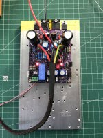
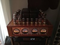
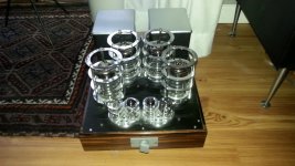
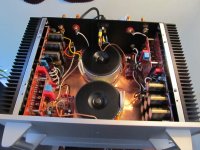
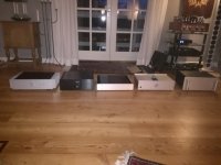
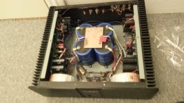
Here are a few of the amps I build
It has been very interesting to follow all your thoughts and experimentations and , as I said , I fully understand the urge to try to make things better.
I am surprised, however , to hear you build the original and that it was unstable? Did you use all the correct components? The two I made was completely stable after changing defective and wrong components. It would be sad, if this construction gained a reputation of being difficult to build and unstable, as this is not the case IMHO. As mentioned above, I have build countless DIY constructions and this one is one of the most easy to build and get stable. Not even one thing to adjust..
And I am still surprised that so few people have build the original. It really is a shame because it is so good. There have been other threads with DIY amps that was not nearly as good (or easy) as this one filled with folks that actually build them.
Here are a few of the amps I build
Attachments
Last edited:
I am trying to summarise how this behaves with oscillation: There is the problem of detail mapping in electrical transmission, which means that there are "steps", needle impulses and other signal elements that are outside our hearing range as a continuous tone, but are interpreted by humans as a complex signal.
Example (from practice):
A person is recording an audio book, in which the consonants are less beautiful in sound. My approach is to apply a frequency filter in the range of 15 kHz, which is about the same as the rise of common microphone capsules. The result: the consonants sound balanced.
Here I used a filter that is above the audible range of the sound master, but he heard the effect of this filter.
For this reason, I looked into the question of the current delivery capability of systems, because I noticed that there is a sonic correlation between the impulse strength of capacitors and their influence on the imaging performance of analogue circuits. So it makes sense to equip the power supply on the amplifier board with capacitors of very high pulse strength. This in turn also has the effect that the circuit is more likely to oscillate, since I am installing high-frequency capacitors that enable oscillation behaviour.
Now, in the original by Tibi, the usual foils are installed on the operational amplifier to supply current, whereas Tibi uses the usual MKS here, i.e. polyester foils that are metallised. If you build a test circuit by choosing a very high-quality operational amplifier (OPA1611) and use it as a preamplifier, for example for impedance matching between source and power amplifier. Then you can hear very clearly how the power supply circuit sounds. Here, a current regulator, as it is built on the amplifier board, is a variant of this. If one now changes the foil resistors on the operational amplifier, one can notice that the pulse strength and the construction of the capacitors have a stronger effect than the conductor length - by this I mean that a conductor length between 5 mm and 50 mm can be compensated by the conductor size.
Experiments like this have led me to use the FKP2 as a compromise between size, cost and sonic imaging performance.
With this explanation, I want to explain why, on the one hand, Tibi's original works stably with the capacitor quality used there and, on the other hand, why it is possible to increase the amplifier's imaging quality, but why compensation measures are needed to avoid oscillation, which do not reduce the imaging performance gained. Therefore, in the many variants that I built up in one year, I have also had very sobering results that were stable but represented a step backwards in terms of sound.
It is clear to me that removing the resistor between the output GND and the input GND is the easiest way to force the amplifier to play clean and to massively minimise the oscillation potential. However, in doing so I lose the charm of the design. There is simply the issue that there are no perfect recordings and no perfect speakers, and that's where you have to add your personal touch to the design. With my version 12 of the Q17 I create a particularly high resolution, a very airy free sound and a fine melting with a subtle warmth in the imaging. In saying this, I in no way wish to question the genius of the original, since Tibi himself writes that he also wants to keep the amplifier inexpensive. This is undoubtedly such an amplifier, which in its simplicity, its inexpensive components performs exceptionally well and thus plays in the top league of amplifiers.
Now about the components. I did not install a fake MosFET, but the original with BS250 and the 2N7000 (which I also remeasured). Since the 2N7000 failed during the tests, I switched to the ZVN4206A and ZVP2106A. However, from the beginning I didn't get an OPA1641 and therefore built the amplifiers with OPA1611, one version also with the OPA1642, OPA1656 and OPA1612. In one version I also used FKS (polyester film capacitor with metal foils) for voltage stabilisation and changed this immediately, because I missed too much sound spectrum (the imaging performance dropped back a lot). I did not install and test the MKS because of my previous experience, which was some years ago.
The active rectifier did not improve or worsen compared to 8 MUR810s, it seems to be neutral in terms of sound. What is clear, however, is the sonic influence of the large electrolytic capacitors on the rectifier board. This influence can affect the sound in such a way that an unfavourable choice reduces the rest of the work and the quality of the amplifier.
Regards Tim
Nice! Still I would use a bipolar capacitor for C2, a DC blocking coupling cap and RC input filter at the input certainly with OPA1641.
Coincidentally I have a defective and mistreated 405 with 1 blown channel in front of me but do these boards fit in an original Quad 405?!
Very rare to hear of a blown quad board
Tim
I still say. Build the original , carefully with good solderings, use only genuine parts from the BOM list use the OPA 1641 and use good transformers. Now put it in a good metal case and listen. You will not be dissapointed. It performs so much better than one would expect.
Now if the itch is still there to try to improve, make another set and go crazy on them, but keep the original as reference.
I must confess, I made a small changes. I use two BlackGates for C2 C22 and I use a Wima MKP10 for C7. I am going to try different C7 capacitors. No influence on stability at all here.
If you are using an MKP10 for C7, you still have a very long way to go before the amplifier reaches its full potential. Tibi uses Mundorf Silver Gold Oil, I am not a fan of this capacitor, only I realise, with it the amp already sounds classes better. You can't imagine what my amplifiers sound like, that's not what you hear now, but I admit I also thought many years ago that a Technics power amp would be able to reproduce music cleanly. Today I don't think that anymore.
Hi Koldby,
Thank you very much for feedback !
You have an impressive DIY collection ! 👍
Brgds
Thank you very much for feedback !
You have an impressive DIY collection ! 👍
Brgds
No it isn't. Do you mean C2? Or are you using someone else's numbering other than Quad's?C7 is part of opamp negative feedback
In about 17 Quad schematics there is no 1uF capacitor at all, and C7 is 330pF in parallel with 3k3 in the collector load of Tr2, outside the opamp loop. Let's stick to what's well known please.
I am in a thread with 'Quad 405' in the title, by an author who won't even answer simple questions and apparently expects me to read 1430 messages instead. Not very helpful.
- Home
- Amplifiers
- Solid State
- Q17 - an audiophile approach to perfect sound