And the Elna Silmic II RFS. Snif. 😈
Stef.
Hello,
I no longer have a BS250P or ZVP2106A in stock.
The BS250P have become impossible to find.
Is it better to buy ZVP2106A or ZVP3306A to replace Q9 and Q11?
Regards,
Stef.
I no longer have a BS250P or ZVP2106A in stock.
The BS250P have become impossible to find.
Is it better to buy ZVP2106A or ZVP3306A to replace Q9 and Q11?
Regards,
Stef.
I think both ZVP2106A or ZVP3306A will work just fine in Q17. ZVP2106A is closer in specs to BS250P.
Regards,
Tibi
Regards,
Tibi
Another Q17 pair I finished last week.
I have increased R2 and R21 to 10K @ 0.5W. this will reduce LED current to 5-6mA and power dissipated by R2 and R21.
Amplifier is more stable with R32 = 0ohm, therefore R32 was replated with a straight wire.
FQP3N30, now obsolete, was replaced with FQP3N50C.
Regards,
Tibi


I have increased R2 and R21 to 10K @ 0.5W. this will reduce LED current to 5-6mA and power dissipated by R2 and R21.
Amplifier is more stable with R32 = 0ohm, therefore R32 was replated with a straight wire.
FQP3N30, now obsolete, was replaced with FQP3N50C.
Regards,
Tibi

Hello Tibi,
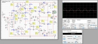
I was wondering if it's really useful to have two ground planes: GND and GNDPWR. If we connect the two ground planes with a strap, it's like creating two islands, which isn't very good.
Concerning the simulation under Multisim that I put on my Github repository. I can't get the circuit to work with an OPA1641. For now, the only one that works is an OPA604U.
Regards,
Stef.
Attachments
Hello Tibi,Another Q17 pair I finished last week.
I have increased R2 and R21 to 10K @ 0.5W. this will reduce LED current to 5-6mA and power dissipated by R2 and R21.
Amplifier is more stable with R32 = 0ohm, therefore R32 was replated with a straight wire.
FQP3N30, now obsolete, was replaced with FQP3N50C.
Regards,
Tibi
You are really funny.
It is clear that R32 is responsible for the Q17 having an old scool sound and that R32=0 Ohm eliminates this issue.
With your current mod the amp should have an offset of about 0V, have you measured that?
I have recently been investigating the switching pulses of the output MosFET via the feedback loop of the amplifier, there is a transfer via R6 to the input GND and thus a feedback into the input. You have now stabilised this with R32=0 Ohm via the power supply. All you need now are high-quality capacitors to reveal the full acoustic potential of the circuit.
I would be interested to know, how does your new modification sound with your loudspeakers relative to older versions of the amplifier?
Regards Tim
FQP3N30, now obsolete, was replaced with FQP3N50C.
Hi Tibi,
Obsolete too.
https://www.mouser.fr/ProductDetail/onsemi-Fairchild/FQP3N50C?qs=VOMQJJE%2BBNki2gSsJvOsEg==
In fact, it seems that the entire FQA and FQP range from Fairchild is in the process of being discontinued. The pension funds that have bought the component manufacturers since the 2000s are melting the "household" to maximize profits. This is all going to end badly for the industry.
Regards,
Stef.
Even with R32=0ohm, power plane still need to be separated by small signal plane, in order to avoid high current return into small signal plane.Hello Tibi,
I was wondering if it's really useful to have two ground planes: GND and GNDPWR. If we connect the two ground planes with a strap, it's like creating two islands, which isn't very good.
Concerning the simulation under Multisim that I put on my Github repository. I can't get the circuit to work with an OPA1641. For now, the only one that works is an OPA604U.
Regards,
Stef.
Regards.
Tibi
Offset is ~0,1mV and the sound is terrific.Hello Tibi,
You are really funny.
It is clear that R32 is responsible for the Q17 having an old scool sound and that R32=0 Ohm eliminates this issue.
With your current mod the amp should have an offset of about 0V, have you measured that?
I have recently been investigating the switching pulses of the output MosFET via the feedback loop of the amplifier, there is a transfer via R6 to the input GND and thus a feedback into the input. You have now stabilised this with R32=0 Ohm via the power supply. All you need now are high-quality capacitors to reveal the full acoustic potential of the circuit.
I would be interested to know, how does your new modification sound with your loudspeakers relative to older versions of the amplifier?
Regards Tim
Regards,
Tibi
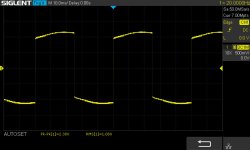
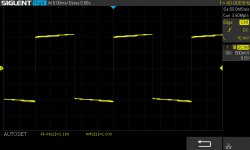
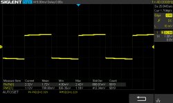
Same here with/without R32 with Mini 1.2. At power on, the DC offset is directly less than 2mV now.
And scope curves seems better...
Not yet tried with a speaker.
😎
Stef.
And scope curves seems better...
Not yet tried with a speaker.
😎
Stef.
Attachments

Last edited:
Hello Tibi
greetings as you have suggested R32- zero ohms
R2/R21- 10K/.5 WATT should i apply these
modifications to the single pair version V1.3
i am building.
warm regards
Andrew
greetings as you have suggested R32- zero ohms
R2/R21- 10K/.5 WATT should i apply these
modifications to the single pair version V1.3
i am building.
warm regards
Andrew
Hello Andrew,
If above was a question, yes R32=0ohm and you may increase R2/R21 to 10K.
Regards,
Tibi
If above was a question, yes R32=0ohm and you may increase R2/R21 to 10K.
Regards,
Tibi
Good evening,
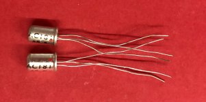
I found two old things for Q12.
Worth a try? They work and would be new.
Is it 2R for R9?
Regards,
Stef.
I found two old things for Q12.
Worth a try? They work and would be new.
Is it 2R for R9?
Regards,
Stef.
Attachments
Last edited:
If AC181's Vbe is around 120mV, than R10 and R13 = 2ohm.
First measure Vbe (at room temperature) and then choose R10 & R13 for ~ 60mA
Regards,
Tibi
First measure Vbe (at room temperature) and then choose R10 & R13 for ~ 60mA
Regards,
Tibi
Hello Stef,Good evening,
I found two old things for Q12.
Worth a try? They work and would be new.
Is it 2R for R9?
Regards,
Stef.
according to the simulation, the Q12 still works at the switching pulses for the Mosfet, which is a frequency of about 16 MHz. The AC181 is reported to have an fT of 3.5 MHz, so it can't do any more amplification in this frequency range, this significantly changes the operation compared to the 2SC1845 with fT > 50 MHz.
Regards Tim
Q12 is part of a CCS with Q6. The main role of Q12 is to provide constant voltage across R13. There is no high frequency amplification involved.
The advantage of a Ge transistor here is that will have a higher thermal drift than a Si one.
Regards,
Tibi
The advantage of a Ge transistor here is that will have a higher thermal drift than a Si one.
Regards,
Tibi
The stupid thing is that theory and practice are always a bit different and we do not have the static voltages and static currents in the circuit that are optimal for the ideal function. It can therefore also make sense to install a transistor with a low fT.
Regards Tim
Regards Tim
Hello,
I measured both AC181s.
Unit 1
hFE=132
Vbe=0.201V
Unit 2
hFE=93
Vbe=0.208V
How old do you think they are?
Regards,
Stef.
I measured both AC181s.
Unit 1
hFE=132
Vbe=0.201V
Unit 2
hFE=93
Vbe=0.208V
How old do you think they are?
Regards,
Stef.
For sure younger than me. 😀...
How old do you think they are?
...
Regards,
tibi
I have increased R2 and R21 to 10K @ 0.5W. this will reduce LED current to 5-6mA and power dissipated by R2 and R21.
Hello,
For R2 and R21, after testing, it would be better to take 1W.
Vishay PR01000101002JR500
Regards,
Stef.
- Home
- Amplifiers
- Solid State
- Q17 - an audiophile approach to perfect sound