Hello!
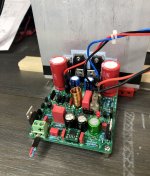
Version 1.3 of the Q17-Mini in break-in...
Everything is fine for now. 😉
I uploaded the files to the Github repository. I have 6 spare 2 Oz PCBs if anyone is interested. I haven't finished the measurements yet but at first glance it will be difficult to do better with this latest version.
For the moment, it is being tested in mono on a speaker. Always such a good mastery of bass and full of detail. 😎
I return to the AC181.
With a Vbe of 0.201V, what resistance value should be expected?
I don't have a 2R in stock anyway.
Regards,
Stef.
Attachments
Last edited:

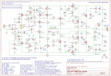
For Vbe of 0.201V, R10 = R13 = 3,3ohm
Regards,
Tibi
Hello Tibi,
I tried on my proto the AC181 on Q12 with R3/R13 = 3R3. I got only 0.124v on resistors. It doesn't seem to work.
Regards,
Stef.
EDIT: oops, R3 or R10?
In fact 120mV is a value more close to what I expect on a Ge transistor. Use R13=2 ohm
Also, you may need to remove R9.
Regards,
Tibi
Also, you may need to remove R9.
Regards,
Tibi
Hi!
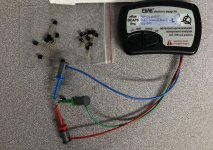
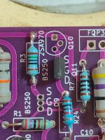
I was fooled by a Chinese seller (litigation in progress).
The seller is: https://www.ebay.fr/usr/satisfyelectronics
The so-called BS250 are in fact anything. Most transistors aren't even Mosfets despite the BS250 marking on the case. The box doesn't even match.
This is the first time this has happened to me.
Regards,
Stef.
Attachments
Hello,
If you're looking for BS250P or ZVP2106A, these two sellers sale stock genuine parts (I personally tested).
ZVP2106A (China)
https://www.ebay.fr/itm/181609632548
BS250P (France)
https://www.ebay.fr/itm/175341996216
Regards,
Stef.
PS: eBay gave me my money back for the fake BS250. 😉
If you're looking for BS250P or ZVP2106A, these two sellers sale stock genuine parts (I personally tested).
ZVP2106A (China)
https://www.ebay.fr/itm/181609632548
BS250P (France)
https://www.ebay.fr/itm/175341996216
Regards,
Stef.
PS: eBay gave me my money back for the fake BS250. 😉
Attachments

In fact 120mV is a value more close to what I expect on a Ge transistor. Use R13=2 ohm
Also, you may need to remove R9.
Regards,
Tibi
Hi Tibi,
What are the good mA values (target) to have for R10 and R13 with AC181?
Currently, I got this:
Power=51v
R9=100R
R10=3R3 ----> 0.180v
R13=2R4 (10R&3R3) ----> 0.136v
Regards,
Stef.
Last edited:
The CCS must deliver around 60mA, therefore 2R4 should be the value to consider.
Regards,
Tibi
Regards,
Tibi
Hi Tibi,
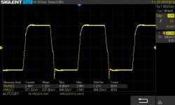
That's what I thought, but I preferred to be sure. So I have about 60mV with R10=3R3 and R13=2R4.
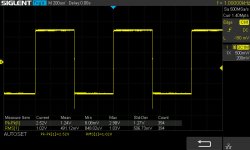
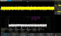
On the other hand, it is not good at scope. I have 1mV more than the normal DC offset (+55%) and the square wave is crap.
Regards,
Stef.
That's what I thought, but I preferred to be sure. So I have about 60mV with R10=3R3 and R13=2R4.
On the other hand, it is not good at scope. I have 1mV more than the normal DC offset (+55%) and the square wave is crap.
Regards,
Stef.
Attachments
Last edited:
Hello,
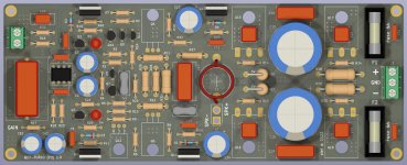
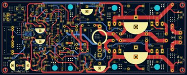
I made a new version of the P2 PCB.
https://github.com/stefaweb/Q17-a-QUAD405-audiophile-approach/tree/main/Q17-TURBO 1.0
I don't plan to have PCBs made at the moment but the files are available if you want to test it yourself.
Regards,
Stef.
I made a new version of the P2 PCB.
https://github.com/stefaweb/Q17-a-QUAD405-audiophile-approach/tree/main/Q17-TURBO 1.0
I don't plan to have PCBs made at the moment but the files are available if you want to test it yourself.
Regards,
Stef.
Attachments
Hi Andrew,Hello Tibi
greetings is this the correct orientation of mosfet
BS250P.
warm regards
Andrew
Please have a good look at at the quality of your soldering job. Very bad flown through. I can garantee a lot of problems when trying toget music out of the build.
Try more heat or better suited soldering material. Clean wires of the parts and/or use some good flux.
I wish your labour ends up successfully, it is certainly worth it!
Ed
Pinout BS 250:
The position depends on the make of the part. Ones you know that, you're able to find out its position. Tibi has written about this in this thread somewere.
The position depends on the make of the part. Ones you know that, you're able to find out its position. Tibi has written about this in this thread somewere.
Hi Stef, Could you elaborate maybe on protection? What is the best (Hifi) approach to include protection whilst connecting to quads own electrostatics as I believe these create a near short to amp when in protection shut down. The 405,306, 606 etc all handle this in there stride of course.Hi!
If you have a plop in the speakers, you can reduce the value of R29/R30. It is however recommended (must) to use a DC protection circuit at ouput to protect (expensive) speakers and stay with 10K.
I will correct R29/R30 on my diagram.
Regards,
Stef.
Any other members care to comment?Hi Stef, Could you elaborate maybe on protection? What is the best (Hifi) approach to include protection whilst connecting to quads own electrostatics as I believe these create a near short to amp when in protection shut down. The 405,306, 606 etc all handle this in their stride of course.
There are several mechanisms here.
1. Quad ESL63s, and ESL57s with the clamp circuit fitted, have a zener string which detects over-voltage and clamps to the sum of the Zener voltages. This is nowhere near a dead short. It is intended to prevent arcing. Any ESL57 without a clamp circuit should be remedied unless driven by a Quad II which can't produce enough voltage swing to trigger it anyway.
2. Quad ESL63s also have an arc-detector aerial which drives a circuit which will apply a dead short via a triac for a 'pre-determined period' when arcing is detected.
3. A Quad 405 will react to a dead short from (2) by blowing the output transistors to protect the DC fuses ;-) The clamp applied by (1) shouldn't bother it much.
Oh!There are several mechanisms here.
1. Quad ESL63s, and ESL57s with the clamp circuit fitted, have a zener string which detects over-voltage and clamps to the sum of the Zener voltages. This is nowhere near a dead short. It is intended to prevent arcing. Any ESL57 without a clamp circuit should be remedied unless driven by a Quad II which can't produce enough voltage swing to trigger it anyway.
2. Quad ESL63s also have an arc-detector aerial which drives a circuit which will apply a dead short via a triac for a 'pre-determined period' when arcing is detected.
3. A Quad 405 will react to a dead short from (2) by blowing the output transistors to protect the DC fuses ;-) The clamp applied by (1) shouldn't bother it much.
This goes against my investigation of the 505-2 circuit.
I pulled this from another discussion on modding the 405/405-2 ?
[IMG alt="jan.didden"]https://www.diyaudio.com/community/data/avatars/s/1/1603.jpg?1660657501[/IMG]
jan.didden
Member
Paid Member
2006-01-19 12:01 pm
#10
Zombie said:[snip]What concerns the current limiters, gently desolder N1 and N2 and politely say goodbye before they enter the garbage bin (you are not using ESL57 are you?)...
[snip]
These are not current limiters. These are safe operating area limiters. One of the main differences btween the -1 and the -2 is in the improved protection system. The -2 system limits the operation area of the output stage to protect blowing up the output devices. They do not just limit current to some arbitrary value. Throwing them out is a bad idea; they will not limit the power under normal conditions, but will protect the amp in case of shorts and prolonged overload.
Jan Didden
- Home
- Amplifiers
- Solid State
- Q17 - an audiophile approach to perfect sound