These calculations are meaningless. You need a clear idea of the source impedance that is feeding these components. It is typically 5-10K for solid state preamps but could be hundreds of K for a valve preamp.For ejp: what do you think of the filter with R33 = 100R and C20 = 680pF (2.3MHz at 100R or 45KHz with 5100R at input)?
Hello ejp,
I have the impression that we are not talking about the same thing.
For me, a preamp has an output impedance of a few hundred Ohms at most, not ten KOhms. Generally 100R or 600R with modern gears. Afterwards, we can of course find higher with certain old equipment in particular, with valve preamp (>1KOhms).
Stef.
So you need to specify which preamps you are thinking of, and their expected output impedance.
Examples of what I cited are legion. I am dealing presently with an ancient valve preamp whose output comes from a common-cathode valve stage, via a high impedance filter, then a high impedance balance control, then a high impedance volume control. Output impedance 50K at an absolute minimum.
You will never find a valve preamp with output impedance as low as l1K.
Hello!
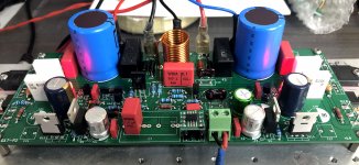
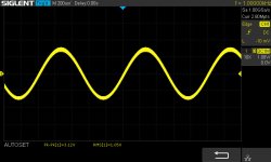
I built the prototype of Q17-P2. At first sight, the card works but it oscillates alas. This is the sinus with see on the scope screenshot below.
I have 35mV of offset at the output with the voltmeter connected directly to the HP terminals. More if I connect an 8R load connected with the scope.
Nothing is very hot.
I have to find where it comes from which is not an easy task. 😆
Stef.
Hello Stef,
Your measured vibrations correspond to the simulation.
There are different ways to reduce these oscillations, one is to dampen them with capacitors influenced the signal path before the end transistors, but also already by a stabilization in the input, like your input filter.
For the single power section I have been able to solve it in a particularly audiophile way, for the variant with more power transistors I have not yet found a good solution that has advantages over the simple variant.
Regards Tim
Hi Tim,
With version 1.2 of the Q17-Mini, I no longer have any oscillation at all (with or without the input filter after more test). The offset is 2/3mV. The optimization of the PCB and some components seems to have played.
For the P2, I don't really know where it comes from. I really spent a lot of time optimizing the PCB. Whether I look at the scope at the output of the opamp (pin 6) or at the HP terminal, I see it (with not the same amplitude of course).
For the moment, I haven't wired the 100uF/1uF couple on each power transistor (pin 2 of FQAs). I also didn't wire C29 and C30 (led).
Do you have any suggestions for trying to add components directly to the PCB?
I can also try to solder the opamp directly on the PCB but I don't think it comes from there since I have the same thing on the Q17-Mini.
The schematic is here: https://github.com/stefaweb/Q17-a-QUAD405-audiophile-approach/blob/main/Q17-P2/Q17-P2-schematic.pdf
Stef.
Attachments
Hi, I'm back.
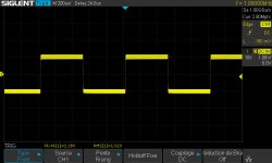
The funniest thing is that even with the big oscillation at 11MHz that you can see on the scope, I plugged the P2 card on a speaker in mono. With no source, no noise on the tweeter. With a source, the P2 appears to be playing music. 😉
I changed C7 by a Wima MKP2 100v (same as in the Mini). No change. I added 100nF in SMD on the back close to the opamp (C4' and C6'). No change.
Not yet tested with REW.
Stef.
Attachments
Last edited:
Dunno what the bottom pads look like, but the right leg of c1 and right leg of the resistor to its left look a little dry...Hi, I'm back.
The funniest thing is that even with the big oscillation at 11MHz that you can see on the scope, I plugged the P2 card on a speaker in mono. With no source, no noise on the tweeter. With a source, the P2 appears to be playing music. 😉
I changed C7 by a Wima MKP2 100v (same as in the Mini). No change. I added 100nF in SMD on the back close to the opamp (C4' and C6'). No change.
Not yet tested with REW.
Stef.
Hello Stef,
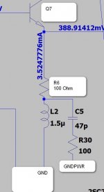
I have tried something new, here the signal path of the oscillation is via the input GND, which will blocked by a filter. In the simulation I can lower the level at 11MHz by 13 dB. Here I disconnect the R6 from GND and connect it via an inductor with 1.5 uH and discharge the high frequency interference via a subber adjusted to the frequency against GNDPWR. The capacitor is chosen rather high with 47pF, but I expect that you still have one of these to realise a flying setup. Compared to earlier experiments, I can assure you that the oscillations will not increase and therefore your amplifier will remain whole. What the simulation does not answer satisfactorily for me is whether it is sufficient to be able to damp the oscillation completely.
With my single solution, the simulation looks even better, but the concept is also even more complex.
Regards Tim
Attachments
You have already wound many air coils for the output, just add two more turns and then it will have about 1.5.
self wounded aircoil or something like this
https://www.reichelt.de/smd-keramik...-1812as-1-5--p105566.html?&trstct=pos_1&nbc=1
without Ferrit and Low resistent
Last edited:
Hand made coil will be too big. 😉
A true hole version will be easiest to use.
Found theses.
https://www.mouser.fr/ProductDetail/Bourns/RLB0608-1R5ML?qs=qtLBrsE9qZI5aFG2TVUthA==
https://www.mouser.fr/ProductDetail/807-1537-16J
Stef.
A true hole version will be easiest to use.
Found theses.
https://www.mouser.fr/ProductDetail/Bourns/RLB0608-1R5ML?qs=qtLBrsE9qZI5aFG2TVUthA==
https://www.mouser.fr/ProductDetail/807-1537-16J
Stef.
Last edited:
my first two coils for this test are running in one of the amplifiers, these are air core coils wound in multiple layers with 4mm inner diameter, this is definitely suitable for an experimental setup. The point is not that it looks nice, but how effective it is. You can of course order some, I have my setup fitted with 3.3uH, but that is not optimised for 11MHz.
And think about the distortion spectrum when you buy inductors, if they don't work cleanly in the MHz range, such an inductor is useless. Since the SMD coil I use is very large, it is very easy to fix it with a large wide soldering iron.
Regards Tim
And think about the distortion spectrum when you buy inductors, if they don't work cleanly in the MHz range, such an inductor is useless. Since the SMD coil I use is very large, it is very easy to fix it with a large wide soldering iron.
Regards Tim
- on bard filter capacitors have been increased to 4700uF. I think this is maximum value for this footprint. In terms of sound, this caps matter a lot, so you may voice your amplifier by changing them.
Is there a recommandation for this capacitor with a lifespan of more than 2000 hours?
Thanks.
R22 should protect against microphone effect from the capacitor C20.I also wonder if the R22 is still useful since there is the R33 in front since I added the LPF input.
Stef.
the most successful option when R22=R33.
I look at the circuit and ask myself the question - why do we need a base current compensation bridge if there is no current in the output stage on the mosfets?Schematic for Q17 and his power supply.
- Home
- Amplifiers
- Solid State
- Q17 - an audiophile approach to perfect sound