Github was updated with latest KiCad files and gerber for 2 pair output.
PCB modifications are mainly aesthetic as follow:
As I already mentioned in the first post of this thread, please give at least 300h burn in, before listening.
Q17 sound far better than very expensive commercial amplifiers. The sound is precise, dynamic, harmonic reach and very musical. Bass control is in very top league.
I'm confident that Q17 is one of the best amplifiers you may build from scratch.
Enjoy !
Regards,
Tibi


PCB modifications are mainly aesthetic as follow:
- a new top ground plane was added. This will slightly improve power supply and output section
- some traces have been enlarged
- all traces have been rounded
- component marking is now clear and visible making mounting a breeze
- on bard filter capacitors have been increased to 4700uF. I think this is maximum value for this footprint. In terms of sound, this caps matter a lot, so you may voice your amplifier by changing them.
As I already mentioned in the first post of this thread, please give at least 300h burn in, before listening.
Q17 sound far better than very expensive commercial amplifiers. The sound is precise, dynamic, harmonic reach and very musical. Bass control is in very top league.
I'm confident that Q17 is one of the best amplifiers you may build from scratch.
Enjoy !
Regards,
Tibi

Hello Tibi,
I have some advice for you on connecting an Auricap XO capacitor in the circuit for C7.

Auricap gives a connecting method as shown on this link.
https://www.justradios.com/auriINSTALL.html
If I understand, the foil would be on the black side (outside foil) so if I go back to the discussions we had on this subject, outside foil would be put on the op-amp side. On the other hand, the documentation cited above says to do the opposite.
Where is the truth ?
Stef.
I have some advice for you on connecting an Auricap XO capacitor in the circuit for C7.
Auricap gives a connecting method as shown on this link.
https://www.justradios.com/auriINSTALL.html
If I understand, the foil would be on the black side (outside foil) so if I go back to the discussions we had on this subject, outside foil would be put on the op-amp side. On the other hand, the documentation cited above says to do the opposite.
Where is the truth ?
Stef.
https://www.justradios.com/auriINSTALL.html
I fully agree with this. The black lead - capacitor outside foil - must always be connected to lower impedance. In our case operational output is the lowest. There is no contradiction between my implementation and document mentioned by you.
Regards,
Tibi
I fully agree with this. The black lead - capacitor outside foil - must always be connected to lower impedance. In our case operational output is the lowest. There is no contradiction between my implementation and document mentioned by you.
Regards,
Tibi
I'm having a hard time understanding the doc then.
So the side with the black dot is fine on the opamp side. This matches what I wrote on my PCBs.

I hope it's worth it compared to a simple Wima MKP because the Auricaps are worth the skin of the buttocks.
Stephane
So the side with the black dot is fine on the opamp side. This matches what I wrote on my PCBs.
I hope it's worth it compared to a simple Wima MKP because the Auricaps are worth the skin of the buttocks.
Stephane
I'll try to explain, so things may be a bit clearer. My comment is in bold.
"1) In all coupling applications the input to the Auricap should be the black lead and
connected to the signal source or circuit output with the red lead continuing on to the
next circuit input."
To have a proper energy transfer between source and amplifier, the source must always have lower impedance than amplifier input, therefore the black lead will go to source.
"2) In all power supply decoupling applications the outside foil or black lead should
be connected to ground and the red lead connected to the voltage to be decoupled.
This is true for decoupling either voltage polarities."
This is clear.
"3) In loudspeaker crossover applications, if the Auricap is in series, like feeding a
tweeter, the black lead connects to the input binding post and the red lead connects to
the tweeter.
Where the Auricap is in parallel, as typically used for woofers, the black
lead connects to the speaker connection that connects to the input binding post and the
red lead connects to the other speaker terminal. Follow these same rules for midrange
connections where you will have a combination of both."
Amplifier output impedance must be lower than speaker impedance, therefore the black goes to amplifier output.
And everything is summarised in this:
"The idea is to always have the outside foil connected to the lower impedance to
provide outside foil shielding to noise. Circuit outputs are always lower impedance
than inputs and should be connected to the outside foil."
Regards,
Tibi
Last edited by a moderator:
I've been following this topic for some time. This amplifier is on my list. The layout turned out really nice.
Greetings!!
Greetings!!
Hello,
I need your help with some calculations.
In the new PCBs I made, I added an (optional) LPF before the op-amp. Placing this LPF added an 860R (R33) + 100R (R22) resistor into the circuit.
This creates an attenuation on the input sensitivity of the circuit.
I would have liked to recalculate the value of resistor R17 for an input sensitivity of 0.75v (R17 = 3K3) and 1.5v (R17 = 7K32).
Stef.
https://github.com/stefaweb/Q17-a-Q...blob/main/Q17-Mini-1.2/Q17-Mini-schematic.pdf
I dion't know where you got 234KHz from. Ft for 860R+1nF is 185.06KHz assuming zero source impedance, which you can't. If you use a more realistic 5K source impedance it becomes 5860R+1nF, giving 27KHz. Far too low. I don't know what R22 is for either.
The extra attenuation caused by 860R+100R is only 4%. Not worth worrying about.
The extra attenuation caused by 860R+100R is only 4%. Not worth worrying about.
Hello!
R17 permit to change the opamp gain.
R22 is to protect FET opamp (optional). Not needed for other type of opamp.
I must have crashed when calculating the first LPF. I'm not very good at math. Well, the R33 has 860R seems wrong.
What will be the right R33 value for a correct filter not to low?
Stef.
R17 permit to change the opamp gain.
R22 is to protect FET opamp (optional). Not needed for other type of opamp.
I must have crashed when calculating the first LPF. I'm not very good at math. Well, the R33 has 860R seems wrong.
What will be the right R33 value for a correct filter not to low?
Stef.
I also wonder if the R22 is still useful since there is the R33 in front since I added the LPF input.
Stef.
Stef.
Oops, I did a mistake on the diagram. The right value on my note is R33 = 680 Ohms for C20 = 1nF.
The error is ONLY on the Q17-P2 diagram. The Q17-Mini diagram is ok.
I've to correct that if 680R is correct. I do not know if I had taken into account the input impedance.
Stef.

The error is ONLY on the Q17-P2 diagram. The Q17-Mini diagram is ok.
I've to correct that if 680R is correct. I do not know if I had taken into account the input impedance.
Stef.
Last edited:
Stef,
If you want an input LPF, I suggest you to set this at a higher frequency, let's say 1MHz or higher.
Formula is Fc=1/2¶RC where Fc is frequency cutoff.
For R33=100ohm you have C20=1,5nF
On other hand, I strongly do not recommend a LPF at Q17 input.
I guess that R22 is a "gate stopper" at operational non-inverted input. This is not needed. If you still want to have it, then add a resistor to inverted input as well.
Regards,
Tibi
Last edited by a moderator:
I will remove R22 in next release. It will give me a little more space. 😉
Once I tried without or with the input LPF on the Q17-Mini. I don't hear any difference.
Stef.
Once I tried without or with the input LPF on the Q17-Mini. I don't hear any difference.
Stef.
Hey Stef, any idea when this layout will be ready? Really excited at the layout with different options as well as spread of the mosfets on longer side of the PCB 🙂 Very well thought out ideas being implemented.HI Tim!
I'm back after a break for personal reason.
I'm glad your latest version is working the way you want it to.
On your web page, I couldn't find the diagram of your version of the Q17?
Regards,
Steve.
ps: My own version of the Q17-P2 is still in the works but I've done a lot of mods on the PCB lately. C7 footprint can fit a Auricap capacitor now.
Q17-P2
https://github.com/stefaweb/Q17-a-QUAD405-audiophile-approach/tree/main/Q17-P2

Thanks
Hello manniraj,
I've ordered 5 boards of the 1.0 version. Will have them next week. Not sure that this topology will work. This version with the mosfets at each end could wobble. To see in real life.
For ejp: what do you think of the filter with R33 = 100R and C20 = 680pF (2.3MHz at 100R or 45KHz with 5100R at input)?
Stef.
Hello!
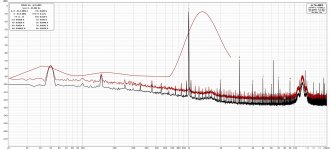
I did a test with a Q17-MIni 1.2 card with and without LPF at the input. The settings are exactly the same. I send 40 mVrms 1KHz sinus at input and I got 1 Vrms at output.
The first curve is without LPF.
The second curve is with an LPF (R33 = 100R and C20 = 680pF FKP2).
Resistor R22 is strapped.
We notice that the THD values are better with the LPF. There is also a big level difference on harmonic number 3. Less on the others harmonics.
Stef.
EDIT: I forgot too. Without the LPF, I have 39mV of DC output and with the LPF, I have 3mV of DC output. The opamp is on a DIP socket. May be this cause a problem.
Attachments

Last edited:
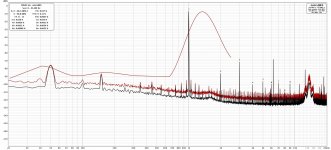
Another curve.
1MHz LPF (R33 = 100R and C20 = 1.5nF FKP2)
I analyzed the behavior of the output DC offset a bit better.
Without LPF at the input, the offset remains at 39mV. With the LPF, when I turn the board on it starts at 39mV and slowly drops to 3mV in a few seconds (6/8 secondes). After that it doesn't move.
Stef.
Attachments
- Home
- Amplifiers
- Solid State
- Q17 - an audiophile approach to perfect sound