Each group buy THT pcb was shipped with few bonus transistors.
There is one 2SC2240GR that must be used in place of Q7.
There are two 2SC2240BL that must be used in place of Q3 and Q12.
There are two BC560C, measure hfe and use the higher one in place of Q10.
You may use many other parts, but please take care on pinout. The PCB was designed for parts mentioned in schematic.
Looking forward to see some nice implementations and feedback will be much appreciated.
Regards,
Tibi

I would also love to see some listening feedback ! I am pretty sure that many of you guys have some pretty interesting audiophile gears to compare it with !
Unfortunately for me, I'll have to wait few months untill i get the opportunity to build it.
Call ne nuts if you like but, i dreamt about the amp last night. And it wasn't bad at all !!!
I pictured it in a point to point flywire/scaffold fashion with shinny copper wires inside a plexiglass box, with a beautiful wooden base engraved in gold "Q17, the ultimate audiophile peace of art" hehehehe ! Of course, it was stunning next to a fireplace which i don't have !
unconsciously, I am probably tired of seeing metal bricks amps everywhere in my home 🙂
Good day Tibi!You may use many other parts, but please take care on pinout. The PCB was designed for parts mentioned in schematic.
Looking forward to see some nice implementations and feedback will be much appreciated.
Regards,
Tibi
R 26 (22 Ohm) and R27 (22 Ohm) are two resistors in series. Both 1Watt.
So replacable by one piece 44 Ohm (5Watt).
The nearest value in the Mills catalogue (low induction types) is 47 Ohm /5Watt.
Could I use this one, in spite of it beeing not the exact same value?
I hope it will be a compact substitute....
Regards,
Ed
Hello Ed,
You need to match 44ohm value. R26 and R27 are there to use E standard (as per IEC 60063:1963) and to offer proper power dissipation.
Same with R24 & R25.
https://www.partsconnexion.com/MILLS-64551.html
Regards,
Tibi
You need to match 44ohm value. R26 and R27 are there to use E standard (as per IEC 60063:1963) and to offer proper power dissipation.
Same with R24 & R25.
https://www.partsconnexion.com/MILLS-64551.html
Regards,
Tibi
Thank you, Tibi!Hello Ed,
You need to match 44ohm value. R26 and R27 are there to use E standard (as per IEC 60063:1963) and to offer proper power dissipation.
Same with R24 & R25.
https://www.partsconnexion.com/MILLS-64551.html
Regards,
Tibi
I suggested to use only one resistor because of lack of space. But I can place them vertically of course. I will do so.
Do you suggest R25 and R24 to use low induction types as well, or is there no gain in doing so?
Another q is: In the Q17.2 version there are two extra C's of 100nF. C18 and C19.
These are not mentionned in the 'extra part' addendum of the double output pair amp.
Are they the same as C26-C27?
I saw you used a different C in your latest setup-picture.
Regards
Ed
Parts inside current dumping bridge must be high quality and low tollerance.
R24 and R25 do not need to be special.
C18 and C19 can be same as C26 and C27.
My Q17 was made by recovering parts from a prototype.
Regards,
Tibi
R24 and R25 do not need to be special.
C18 and C19 can be same as C26 and C27.
My Q17 was made by recovering parts from a prototype.
Regards,
Tibi
Thank You!Parts inside current dumping bridge must be high quality and low tollerance.
R24 and R25 do not need to be special.
C18 and C19 can be same as C26 and C27.
My Q17 was made by recovering parts from a prototype.
Regards,
Tibi
Saves me a lot of coins....
Regards,
E
Hello,
I have now applied the findings from my DAC development to the Q17 and added two more capacitors. The reason is that the Z-diode noise is dependent on the Z-voltage, so I have now modified the current smoothing so that 14V is smoothed to ground via a FKP2 4.7nF before the last 4.7V Z-diode follows.
Also, for the more budget conscious, I added solder locations on the PCB for normal capacitors for C7. Here it is a combination of Wima MKP10 and Wima FKP1, which I could determine as very high-quality in my experiments.
Gerber file: http://lautsprecher.tuschell.de/DIY/Q17/GerberQ17-V12-194.9x79.9mm.zip
Regards Tim
Attachments
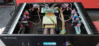
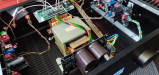
Also my version with parallels final transistors is ready and singing .
Will put here some photo of my amplifier.
Will put here some photo of my amplifier.
Attachments

Hi everybody!
Looking for two "Tibi's" boards, the double output version. (f2)
Who has some left-overs.
I could help with some one fet-output boards...
Looking for two "Tibi's" boards, the double output version. (f2)
Who has some left-overs.
I could help with some one fet-output boards...
Still getting parts together before I start the build.
….And deliberating my case layout between building as identical mono blocs, with either internal or -if I can find the right quality cases cheep - utilising an external power supply layout per amp.
I’m thinking if this I going to be “ultimate” would a balanced input be difficult to implement with the boards??
A new small batch (10 boards 2oz gold + 10 normal) is in production. Subscribe here if you are interested https://docs.google.com/spreadsheet...8LCgoa5Lb6z94TKbopFC7S6aw/edit#gid=1638000354Hi everybody!
Looking for two "Tibi's" boards, the double output version. (f2)
Who has some left-overs.
I could help with some one fet-output boards...
Expect to ship at the end of this month.
Regards,
Tibi
It seems that BS250 is very hard to source.
Alternatives:
https://ro.mouser.com/ProductDetail/Microchip-Technology/VP2106N3-G?qs=NZF3WWV0eEGNFUSyHi4JQQ==
https://ro.mouser.com/ProductDetail/Diodes-Incorporated/ZVP3306A?qs=vHuUswq2%2Bsyljxw/l1wUQg==
https://ro.mouser.com/ProductDetail...-Atmel/VP0106N3-G?qs=JxpGtEvqY41VIHjlZFR9vQ==
https://ro.mouser.com/ProductDetail/Microchip-Technology/VP2206N3-G-P003?qs=Q7eD95YXruaoUlFzWRiXtg==
Regards,
Tibi
Hello,
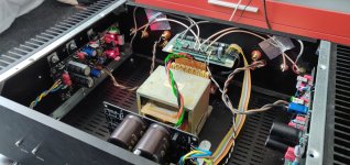
I have now disassembled and rebuilt the old Q17, it is unchanged a setup with 2x 24V transformer.
My thesis about the defect was correct, in the one amplifier, the power MosFET were dead. Therefore, this module has destroyed about 900W of current, so that the fuse protected the amplifier from fire. The transformer survived this. Acoustically there was nothing to hear at this moment of the power peak, so the speakers did not get a current pulse during this.
The new setup sounds lovely, flattering to the ear and with a nuance of warmth. It has thus become incredibly emotional, despite the outstanding resolving quality.
As a source, I have a PCM1794A DAC on a reference layout board, with OP1611 preamp and a particularly elaborate power supply. This is so far the most precise and natural playing analog source I have heard.
I have entered the findings on the Q17 in my public parts list so that a rebuild with different focus is possible.
http://lautsprecher.tuschell.de/DIY/Q17/TeilelisteQ17-V12.htm
I did not change anything on the latest board layout.
Regards Tim
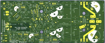
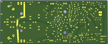
Hi Tibi - ive just ordered my boards, cant wait! Just for interest, what is going on with 'C2' in your attached pics?? Many thanks... TonyFew pictures with latest Q17 pcbs with two output pairs.
Modules have been tested and are performing exceptionally well.
Regards,
Tibi
View attachment 1053071View attachment 1053067View attachment 1053066View attachment 1053068View attachment 1053069View attachment 1053070
On the two ‘C’ spots you can use one non-polar capacitor or two normal C’s in a previously showed confuguration. Here the non-polar is used and the second one (C2) is bridged.
Guys... when it comes to a toroidal, how flexible can it be? My local choices are either 35V or 40V secondaries and either 300 or 500VA...
Any preference? Any values need tweaking? (i'm going for a Q17 2 pair)
Many thanks!
Tony
Any preference? Any values need tweaking? (i'm going for a Q17 2 pair)
Many thanks!
Tony
- Home
- Amplifiers
- Solid State
- Q17 - an audiophile approach to perfect sound