Hopefully last question 🙂
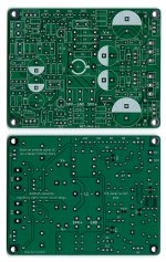
C15/C20 & C16/C21 - all four mentioned on bom - but only footprints for 1 of the pairs? and C26/C27 not on bom - just the same values as say C18?
Sorry to be a pain....
Tony
C15/C20 & C16/C21 - all four mentioned on bom - but only footprints for 1 of the pairs? and C26/C27 not on bom - just the same values as say C18?
Sorry to be a pain....
Tony
Last edited:
Hello Tony,
C15/C20 are two footprints accommodating only one cap
Same for C16/C21.
The value of these capacitors can be as high as 10.000uF if you find ones that fit.
Regards,
Tibi
C15/C20 are two footprints accommodating only one cap
Same for C16/C21.
The value of these capacitors can be as high as 10.000uF if you find ones that fit.
Regards,
Tibi
Just a note!, the list needs to be updated 10 oms resistor part no: 71-CCF0710R0GKE36.Updated first page.
Purchase parts with one click from mouser ->> https://www.mouser.com/ProjectManager/ProjectDetail.aspx?AccessID=1f37a45393
Regards,
Tibi
Now amount 5x please change to 6x. R5, 10, 13, 29, 30, 32 = 6x. now i'm missing 2x
Brgds / Mikael
Hi,
Is there a recommended soft start for this amp? I remember some having problems with fuses blowing along this thread,
regards, E
Is there a recommended soft start for this amp? I remember some having problems with fuses blowing along this thread,
regards, E
Hi,
Is there a recommended soft start for this amp? I remember some having problems with fuses blowing along this thread,
regards, E
This one is very simple and works on my 300 VA tranny. You can put the thing on a small 'vero' board or hardwire it maybe.

Very cool project and results. Just a tip: you can get your DSO to dump the screen contents to a USB key. Alternately by using the Ethernet connection, you can dump the screen to your computer directly.
Thanks Ed.This one is very simple and works on my 300 VA tranny. You can put the thing on a small 'vero' board or hardwire it maybe
My gerbers for a 2" x 2" board of that Elektor softstart circuit if anyone's interested 🙂
https://theslowdiyer.wordpress.com/2015/03/28/project-files-little-helpers-powerhelpers/
https://theslowdiyer.wordpress.com/2015/03/28/project-files-little-helpers-powerhelpers/
Hello all,
There are some test results again, before that the hint that I also use a softstart for the transformer (the same as above in the circuit diagram) and a speaker delay, for this I have put the Gerber for the PCB, as well as the parts list on my Q17 page online.
http://lautsprecher.tuschell.de/DIY/Q17_en.html
After the current tests, I can confirm that even the most audiophile amplifiers have to measure up to the Q17. In the point of low bass it is unbeaten so far, in the point of fine resolution there are serious competitors, but they have their difficulties in the question of long term listening and smoothness. The conclusion is that the Q17 is an extraordinary optimum of the acoustic characteristics that an amplifier must have.
I had to wait a long time for a test with the great NuVista, as I hold this amplifier in high esteem and have come to know it as a particularly good sounding amplifier. In this case, too, the Q17 can subjectively play deeper in the bass and more pleasantly in the treble with a comparable resolution. Of course, the difference in quality is very small, but I can describe the Q17 as particularly mature in sound and sound range.
Let's take a look at the power supply:
I carried out tests with large electrolytic capacitors type: LXZ 1800uF 63V, using 8 pieces to stabilise the current. However, I clearly lost in the low frequency performance, the amplifier played midrange-heavy. Therefore I used KEMET ELH109M063AT4AA, with a comparable capacity they play nicely, but not as dry and neutral as the cheap Yageo capacitors with 4700 uF 63V (4 pieces on the rectifier board and 4 pieces 2200 uF 63V distributed on the Q17 boards) that Reichelt.de sells. I also bought these capacitors over 10 years ago, then in the 10 mF 50V size, and four of them sound fantastic. This is just to add to the consideration of which capacitors are useful for the Q17.
Regards Tim
Last edited:
Hello all,
There are some test results again, before that the hint that I also use a softstart for the transformer (the same as above in the circuit diagram) and a speaker delay, for this I have put the Gerber for the PCB, as well as the parts list on my Q17 page online.
http://lautsprecher.tuschell.de/DIY/Q17_en.html
HI Tim!
I'm back after a break for personal reason.
I'm glad your latest version is working the way you want it to.
On your web page, I couldn't find the diagram of your version of the Q17?
Regards,
Steve.
ps: My own version of the Q17-P2 is still in the works but I've done a lot of mods on the PCB lately. C7 footprint can fit a Auricap capacitor now.

Q17-P2
https://github.com/stefaweb/Q17-a-QUAD405-audiophile-approach/tree/main/Q17-P2
Last edited:
Hello Steve,
In my optimizations, I implemented all the findings directly into the PCB layout, so I can't show you a schematic. Practically, it is only very small changes, additions and adjustment of the quality of components that make the difference to Tiberiu original. For this difference I built many versions, broke many and finally updated older ones to the latest version.
Regards Tim
Q17 prototype in a serious company. Tested and compared !
The top ugly aluminium box have accommodated all my QUAD405 journey, from the very first clone, to the latest version called Q17.
Regards,
Tibi

The top ugly aluminium box have accommodated all my QUAD405 journey, from the very first clone, to the latest version called Q17.
Regards,
Tibi
Hi Tibi!
Beautiful gear!!
By the way, I redid the measurements for the Q17-Mini 1.2. The spectrum is virtually identical to the first version.
On the Github repository, you will find other curves.

There is a 50Hz bump because the power supply was wired in the air without a box and too close from the board.
Stef.
Beautiful gear!!
By the way, I redid the measurements for the Q17-Mini 1.2. The spectrum is virtually identical to the first version.
On the Github repository, you will find other curves.
There is a 50Hz bump because the power supply was wired in the air without a box and too close from the board.
Stef.
I used what I had on hand to power the board and measure it. I was too lazy to open my Q17-Mini amp to use the PSU.
Old toroid 2x34v 160VA + 4 x 10 000uF.

Old toroid 2x34v 160VA + 4 x 10 000uF.
I have made quad405.ljm_ljm, do it! That will certainly then also work with cheaper components.
Even quad707. In fact, he is not so good.
If you have used mx50x2, you will find. He is much better than quad405.
Not to mention really. MOSFET is not good.
If you want to make quad405 Insist on using BJT.
You can use 5200 MJ15024 Or something else. For example, 2SC3858.
However, MOSFET must not be used If you have an oscilloscope, you will understand what I am talking about.
- Home
- Amplifiers
- Solid State
- Q17 - an audiophile approach to perfect sound