.....Hello Tim,
With some of your statements I agree. 🙂
What else can be improved ?
Hello Tibi,
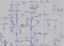
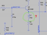
- change Q12 with a n-chanel mosfet . This will require R10 and R13 to be increased to ~50ohm - 60ohm, therefore the gain of Cass A stage decrease, but will become more linear. Current dumping operation will be affected a bit, due Class A stage require gain as high as possible. Here is a light balance I have not tested yet. You may give it a try.
a good idea. What about the following values:
Q12=ZVN4206A
R10, R13=39 Ohm
R11, R12=56 Ohm
Regards Tim
Hello Tim,
Q12=ZVN4206A is OK
Seems that Vgs treshold is around 3V which is OK.
I suggest you to keep R11=R12=47ohm and try to match same current ~60mA. For this R10=R13 will be around 51ohm.
In place of R13 you may use a 100ohm multi-turn trimmer in series with a 39ohm resistor. Adjust till you get across R12 2.82V, than measure resulted resistance trim+R13 and change R10 to match.
Regards,
Tibi
In Ltspice with CTRL+R you can rotate a component and with CTRL+E mirror that component.
It is very important to draw clean schematics, otherwise you get error results or simulation will not start.
Please readraw with stright lines, not multiple, rotate parts and do not leave components not connected.
Regards,
Tibi
It is very important to draw clean schematics, otherwise you get error results or simulation will not start.
Please readraw with stright lines, not multiple, rotate parts and do not leave components not connected.
Regards,
Tibi
Any speaker impedance is variable. You can have a 4ohm/ 8ohm speaker if you mention frequency. A 4ohm@1KHz speaker is more correct. Same speaker may have 20ohm/100Hz.Hi Tibi and Tim,
C7 move is done here on both Mini and P2.
For R31, do you have the value for 4R speaker?
Try R6 on GNDPWR ground will be easy to test with the P2 PCB if you want. See picture. Possible with C1 (but at first I don't see the advantage).
Others tests as LED decoupling or gate stoppers for Q1 and Q4 can also be done very easily.
For gate stoppers, I thought 47R was the minimum?
Stef.
Zobel network is affected by speaker cables as well.
To tune Zobel network you need an oscilloscope.
Disconnect Zobel network from your amplifier and use an external one with different resistors/or capacitors while connected to cables and targeted speakers. Insert a 500mV 20KHz sine on the amplifier and tune Zobel till you get a clean response at speaker bindings.
Regards,
Tibi
Last edited by a moderator:
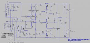
Here is my simulation with mosfet CCS. Notation is different.
Indeed R10 and R13 must be lower. In ~ 27ohm - 30ohm range.
Simulation is OK.
Regards,
Tibi
Indeed R10 and R13 must be lower. In ~ 27ohm - 30ohm range.
Simulation is OK.
Regards,
Tibi
Attachments


Hello Tibi,
Thanks for the explanations on the Zobel.
If the change to transistor Q12 is approved, is there a transistor with the same case as the BD139 (TO-225-3) for use on a heatsink?
Stef.
Thanks for the explanations on the Zobel.
If the change to transistor Q12 is approved, is there a transistor with the same case as the BD139 (TO-225-3) for use on a heatsink?
Stef.
Hello,
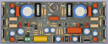
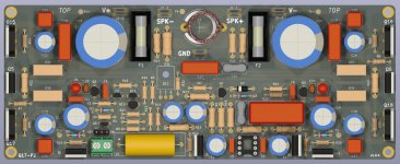
I modified the Q17-P2 diagram/PCB to add gate stopper for Q1 and Q4 (R42 and R43). Fit well. I moved the C0 jumper to have more space.
If needed, I have space to add a small XR7 100nF capacitor for D1 and D4.
This PCB is not yet published. I wait for the PCB prototype to do test.
Stef.
I modified the Q17-P2 diagram/PCB to add gate stopper for Q1 and Q4 (R42 and R43). Fit well. I moved the C0 jumper to have more space.
If needed, I have space to add a small XR7 100nF capacitor for D1 and D4.
This PCB is not yet published. I wait for the PCB prototype to do test.
Stef.
Attachments
Hello Tibi,
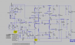
another detail on the topic: GND
In the simulation, you can see that the current across C2 interacts with the current across R6. Therefore the following variant here in the simulation schematic.
I evaluate this variant as a possible test scenario.
Regards Tim
another detail on the topic: GND
In the simulation, you can see that the current across C2 interacts with the current across R6. Therefore the following variant here in the simulation schematic.
I evaluate this variant as a possible test scenario.
Regards Tim
Attachments
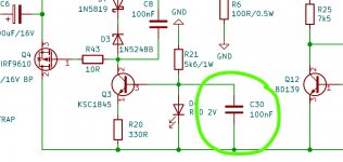
These are decoupling capacitors that may reduce LED noise. The quality of these LED decoupling capacitors is more important than value, this may be in 10nF-1uF range. Also the value may depend on LED type and pcb layout. In many cases, with 100nF you are on the safe side without the need of extensive simulations and calculations.
I would go for ceramic NP0.
Regards,
Tibi
I would go for ceramic NP0.
Regards,
Tibi
Last edited by a moderator:
NPO THT are very big and there is not much choice (and even less availability).
https://www.mouser.fr/ProductDetail...sSlwiRhF8qnFQqSvyFuadADcRAWs9JP3gzDmAxCNCJw==
In SMD 1206 there are many more choices. This is what I put 1206 footprints for C4 / C5 on the back PCB of the Q17-P2. I see if I can do the same for the LEDs.
Stef.
Last version with new C29/C30 for LEDs.
https://www.mouser.fr/ProductDetail...sSlwiRhF8qnFQqSvyFuadADcRAWs9JP3gzDmAxCNCJw==
In SMD 1206 there are many more choices. This is what I put 1206 footprints for C4 / C5 on the back PCB of the Q17-P2. I see if I can do the same for the LEDs.
Stef.
Last version with new C29/C30 for LEDs.
Attachments
Hello,
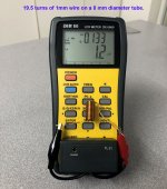
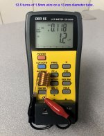
For those who build the Q17-Mini (or the Q17-P2 maybe), I received a new LRC Meter more accurate than my low end Chinese LCR Meter.
There was two too many turns on the coils I had built before. The value is ok for 1KHz and 10KHz.
I am in the process of correcting the documentation on GitHub.
Regards,
Stef.
You can count the number of turns on the photo, in case I counted incorrectly. 😉
Attachments
Last edited:
Hello,
I received an obsolescence notice from Farnell also for the FQP3N30 and the FQP3P20.
Stock up.
Have a nice weekend,
Stef.
I received an obsolescence notice from Farnell also for the FQP3N30 and the FQP3P20.
Stock up.
Have a nice weekend,
Stef.
FQP3P50 with R7=120ohm and FQP4N80 with R8=100ohm
IRF610 and IRF9610 remain available as a decent replacement.
Regards,
Tibi
IRF610 and IRF9610 remain available as a decent replacement.
Regards,
Tibi
Hello Tibi,
I stocked up with 10 of each. 😉
At Infineon or Toshiba, nothing good?
Regards,
Stef.
I stocked up with 10 of each. 😉
At Infineon or Toshiba, nothing good?
Regards,
Stef.
- Home
- Amplifiers
- Solid State
- Q17 - an audiophile approach to perfect sound