Hello Tibi,
I have to ask again, because the amplifier circuit still puzzles me: The Q17 must actually play without the ground resistor (R32 10 Ohm), right?
Regardless of whether you think that's great or not.
Regards Tim
I have to ask again, because the amplifier circuit still puzzles me: The Q17 must actually play without the ground resistor (R32 10 Ohm), right?
Regardless of whether you think that's great or not.
Regards Tim
R32 link power plane to signal plane and his role is to reduce noise from power gnd to signal gnd.
Amplifier will work if you wire R32, or make it 0ohm, but the noise and susceptibility to oscillation may increase.
Regards,
Tibi
Amplifier will work if you wire R32, or make it 0ohm, but the noise and susceptibility to oscillation may increase.
Regards,
Tibi
Hello!
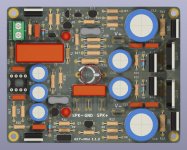
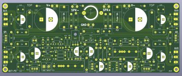
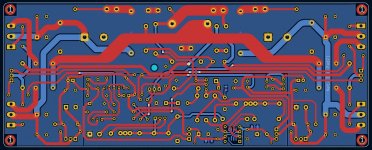
I have released a new version of the Q17-Mini PCB with some improvements.
Have a good day,
Stef.
Q17-Mini-1.1.2 release
https://github.com/stefaweb/Q17-a-QUAD405-audiophile-approach
I have released a new version of the Q17-Mini PCB with some improvements.
Have a good day,
Stef.
Q17-Mini-1.1.2 release
- New vertical footprint for coil
- New SMD footprints on back PCB
- Update C7/R18 circuit position
- Some tracks optimisation
- New 3D and PCB pictures
- Archived version 1.1.1
https://github.com/stefaweb/Q17-a-QUAD405-audiophile-approach
Attachments
Hello Tibi,
I had a question. Why R7 and R8 resistors values are different (R7 = 100R and R8 = 120R).
Stef.
I had a question. Why R7 and R8 resistors values are different (R7 = 100R and R8 = 120R).
Stef.
Man, you really want to squeeze every bit of information form me. 😛
R7 and R8 are different because input mosfet capacitance Ciss is different on N and P channel.
Regards,
Tibi
R7 and R8 are different because input mosfet capacitance Ciss is different on N and P channel.
Regards,
Tibi
This is the case with all parts.
I'm running low stock on parts for Saligny bridges as well and I have few new products not able to put in production.
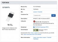
However, Farnell still sell FQP3N30. https://uk.farnell.com/on-semiconductor/fqp3n30/mosfet-n-channel-300v-3-2a-to/dp/2575365?ost=fqp3n30
Regards,
Tibi
I'm running low stock on parts for Saligny bridges as well and I have few new products not able to put in production.
However, Farnell still sell FQP3N30. https://uk.farnell.com/on-semiconductor/fqp3n30/mosfet-n-channel-300v-3-2a-to/dp/2575365?ost=fqp3n30
Regards,
Tibi
I bought mine from Farnell too.
However, the important thing is that they say that the FQP3N30 is obsolete and will no longer be manufactured.
Stef.
However, the important thing is that they say that the FQP3N30 is obsolete and will no longer be manufactured.
Stef.
Here you can see worldwide stock. https://www.trustedparts.com/en/search/FQP3N30
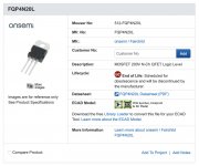
FQP4N20 may be a replacement.
Regards,
Tibi
FQP4N20 may be a replacement.
Regards,
Tibi
FQP3 and FQP4 from ex Fairchild sound really great and took me lot of tests (read time and money) to find them.
Is a shame that almost any audio part, that sound good, get obsolete after few years. 🙁
There are some Toshiba new mosfets, that may fit this application, but I need to simulate, measure and finally listen a lot.
To design a good amplifier you need to listen and compare for each critical part.
Parts matter a lot for those who know how to listen and this take lot of time.
Regards,
Tibi
Hello,
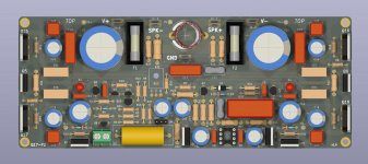
I am pleased to announce the availability of the Q17-P2 PCB.
Gerber files, dedicated diagram and pictures are available on my GitHub repository.
https://github.com/stefaweb/Q17-a-QUAD405-audiophile-approach/tree/main/Q17-P2
The Q17-P2 is a more evolved version of the Q17-Mini that I previously made based on the Tibi diagram.
The Q17-P2 in brief:
Enjoy!
Stef.
I am pleased to announce the availability of the Q17-P2 PCB.
Gerber files, dedicated diagram and pictures are available on my GitHub repository.
https://github.com/stefaweb/Q17-a-QUAD405-audiophile-approach/tree/main/Q17-P2
The Q17-P2 is a more evolved version of the Q17-Mini that I previously made based on the Tibi diagram.
The Q17-P2 in brief:
- Two pairs of FQA Power MOSFET at output.
- PCB size: 190 x 75 mm (230 mm with soldered power resistors).
- DC Fuses incorporated on the PCB.
- Power capacitors of 25mm diameter up to 4700uF.
- Big footprint for most of the important resistors (can fit Dale).
- Big footprint for important film capacitors.
- Optional SMD footprints for C4 and C5 on the back.
- Optional capacitors at the bottom of the FQA transistors.
- New optional resistors to protect opamp inputs.
- Two footprints for C2.
- New C0 footprint capacitor at input to protect against DC.
- Integrated jumper to bypass C0 capacitor.
- New optional D7 Schottky diodes (opamp psu regulation).
- New 13mm 1.2uF coil using 1.5mm wire for better thermal and current performance.
- New test points for power lines and speaker output.
Enjoy!
Stef.
Attachments

Good evening Tibi,
I spent lot of time on it.
I wanted to know if the EXICON ECX10P20 and ECX10N20 are worth the expense with the Q17?
When they will be available. 😉
Otherwise tonight, I plugged the Q17-Mini into a pair of small Dynaudio BM5 (4R and only 87dB sensibility). The Q17 is doing very well. Good mastery of complex filters. I find the sound a little "bright" on the Dynaudio but it is subjective since it was before connected to a pair of old speakers from the 70s (Jennings Contrara) which are far from neutral. In any case, it is very reliable. He turns ten hours a day in background music in my desk.
I will also order some OPA1611 to see if I hear a difference. I generally like bi-polar.
Stef.
Last edited:
With Exicon laterals you can go for 4 pairs of ECW20N20 and ECW20P20. These are double die and do not need source resistor (ballast resistor).
I have implemented Q17 with 4 such pairs at +/-90V achieving 1000W in 4 ohm. A picture is on my twitter account.
These are in stock at https://www.profusionplc.com/type/lateral-mosfet?mnf=exicon
Thanks to high Vds, with laterals, you may achieve impressive power.
On other hand, a single pair of Fairchild's have higher transconductance than 4 pairs of Exicon duble die laterals. Fairchild's will offer low output impedance making Q17 ideal for audiophile speakers.
With laterals, the sound is soft, easy to listen. With Fairchild's, sound is very well defined, with punch and muscle.
For laterals R11 and R12 must be reduced to 20ohm each.
Regards,
Tibi
10R, that's what I marked on the diagram.
I began to ask myself questions. 😉
By the way, with the P2, how many Watt can be output under 8R with 58V?
Stef.
I began to ask myself questions. 😉
By the way, with the P2, how many Watt can be output under 8R with 58V?
Stef.
- Home
- Amplifiers
- Solid State
- Q17 - an audiophile approach to perfect sound