Stef,
Opamp gain calculation is in Q17 project description https://github.com/tvicol/Q17-a-QUAD405-audiophile-approach/blob/main/Project description.pdf
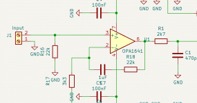
(R17+R18)/R17= 7,6. For 1,5Vrms you may want to set gain almost half, so (3300+R18)/3300=4 => R18=9k9. Closest would be 10K.
Regards,
Tibi
Opamp gain calculation is in Q17 project description https://github.com/tvicol/Q17-a-QUAD405-audiophile-approach/blob/main/Project description.pdf
(R17+R18)/R17= 7,6. For 1,5Vrms you may want to set gain almost half, so (3300+R18)/3300=4 => R18=9k9. Closest would be 10K.
Regards,
Tibi
Tibi,
A patched the circuit with a 22k in parallel with R18 as temporary solution. The level is now closer to what I am used to.
I have an interesting comment from a French engineer around the story.
I don't know what you think about it.
Stef.
A patched the circuit with a 22k in parallel with R18 as temporary solution. The level is now closer to what I am used to.
I have an interesting comment from a French engineer around the story.
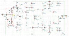
The best will be to add a resistor in series with the V + input. The lack of any series resistance with this input worries me a bit. Self-oscillation with the input transistor sometimes occurs for this reason.
I don't know what you think about it.
Stef.
May I ask the resistor value he propose and may be he kind enough to explain how a series resistor with opamp jfet Vin+ may remove opamp self-oscilations ?
Left or right drawing ?
Regards,
Tibi

Left or right drawing ?
Regards,
Tibi
Last edited by a moderator:
I'll try to send him to you here to talk. My level does not allow me to have an opinion. 😉
Stef.
Stef.
May I ask the resistor value he propose and may be he kind enough to explain how a series resistor with opamp jfet Vin+ may remove opamp self-oscilations ?
Left or right drawing ?
Regards,
TibiView attachment 1009360View attachment 1009361
Hello,
sometimes, an auto-oscillation at very high frequency happens at the input device of an amplifying circuit - may be it tube, bipolar or FET - particularly if its grid, gate or base is connected to ground. It's probably because of the presence of parasitic capacitors and inductors which form a resonant circuit. You often see a little resistor, typically 100 Ω, directly connected at the input of a discrete or integrated amplifying circuit, its aim is to avoid such an oscillation. In fact, it reduces the Q of the resonance. Note that if you connect a little cap to ground at the input after this resistor to build a low pass filter, this oscillation may also happen ! Some guys here may give you more detailed and subtle technical informations.
This is one of the main reasons for which I use in Q17, almost everywhere, grid and base stoppers. On other hand I intentionally not used any LPF at the operational input and this is mainly because I use Q17 in combination with MAYA r2r volume attenuator who have a constant 10K output.
As it is Q17 is an impressive sounding amplifier. For sure it may be improved and I'm looking to see and learn form others what else can be done.
Regards,
Tibi
As it is Q17 is an impressive sounding amplifier. For sure it may be improved and I'm looking to see and learn form others what else can be done.
Regards,
Tibi
May I ask the resistor value he propose and may be he kind enough to explain how a series resistor with opamp jfet Vin+ may remove opamp self-oscilations ?
Left or right drawing ?
Regards,
TibiView attachment 1009360View attachment 1009361
Hello everybody,
I wish you my best wishes for 2022 with health and less mask.
For Tibi, my first question of the year. 🤔
Why on the original diagram C7 is on pin 2 side of the opamp and in the other direction (pin 6) on this diagram which you posted?
Stef.
Attachments
Hello Tibi,
I wish you a happy new year.
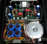
I recently did an experiment with ground resistance, so I came to the question whether it would not make more sense to stabilise the stabilisation capacitors of the + - 15V OPA supply voltage against the output ground.
The reason is based on the consideration of an unbalanced current consumption of the OPA occurring during operation and thus a reduction of the effectiveness of the stabilisation by the capacitors.
Logically, this should not increase ground noise and possibly decrease the DC offset, right?
It could be that this makes the Q17 a bit more sterile in sound, that would be my guess.
Regards Tim
I wish you a happy new year.
I recently did an experiment with ground resistance, so I came to the question whether it would not make more sense to stabilise the stabilisation capacitors of the + - 15V OPA supply voltage against the output ground.
The reason is based on the consideration of an unbalanced current consumption of the OPA occurring during operation and thus a reduction of the effectiveness of the stabilisation by the capacitors.
Logically, this should not increase ground noise and possibly decrease the DC offset, right?
It could be that this makes the Q17 a bit more sterile in sound, that would be my guess.
Regards Tim
Attachments
Hi Tim!
Could you mesure voltage at pin 6 of opamp?
This is to compare with my boards. I have 1.003V.
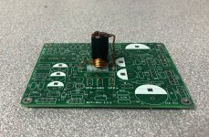
I took advantage of the holidays to install the two coils vertically and I removed the second bridge in parallel on the power supply board. No fun to do but remove those bridges.
Stef.
Could you mesure voltage at pin 6 of opamp?
This is to compare with my boards. I have 1.003V.
I took advantage of the holidays to install the two coils vertically and I removed the second bridge in parallel on the power supply board. No fun to do but remove those bridges.
Stef.
Attachments
Last edited:
Hello Stef,
unfortunately I can't measure them right now, I've handed in my Q17 and have to rebuild new ones.
Tim
unfortunately I can't measure them right now, I've handed in my Q17 and have to rebuild new ones.
Tim
Happy new year 2022 to all diyaudio members !Hello everybody,
I wish you my best wishes for 2022 with health and less mask.
For Tibi, my first question of the year. 🤔
Why on the original diagram C7 is on pin 2 side of the opamp and in the other direction (pin 6) on this diagram which you posted?
Stef.
Indeed I have repositioned C7. This is a large polypropylene capacitor and his position can influence the noise collected by opamp.
I have redesigned the pcb and repositioned C7 such way that outer foil is connected to operational output. This way I minimise the noise collected by "antenna" created by the large foils of this cap.
Regards,
Tibi
Hello Tim,Hello Tibi,
I wish you a happy new year.
I recently did an experiment with ground resistance, so I came to the question whether it would not make more sense to stabilise the stabilisation capacitors of the + - 15V OPA supply voltage against the output ground.
The reason is based on the consideration of an unbalanced current consumption of the OPA occurring during operation and thus a reduction of the effectiveness of the stabilisation by the capacitors.
Logically, this should not increase ground noise and possibly decrease the DC offset, right?
It could be that this makes the Q17 a bit more sterile in sound, that would be my guess.
Regards Tim
Opamp operation current is very low, under 5mA per rail.
On other hand, I do not like the idea of having input ground polluted by output power ground.
Regards,
Tibi
Operation output is lifted to ~1Vdc due Qt Vbe, voltage across R1 and voltage across R6. Voltage across R1 is ~0, so you have = 0.6V +(100 x 4ma)= 1VHi Tim!
Could you mesure voltage at pin 6 of opamp?
This is to compare with my boards. I have 1.003V.
I took advantage of the holidays to install the two coils vertically and I removed the second bridge in parallel on the power supply board. No fun to do but remove those bridges.
Stef.
In other words, it is normal. 🙂
IMHO, mounting coil vertically is the best position.
Regards,
Tibi
Thanks Tibi.
Thanks Tibi.
And mounting the coils vertically makes them heat less. 5°C less than in horizontal position.
Stef.
Operation output is lifted to ~1Vdc due Qt Vbe, voltage across R1 and voltage across R6. Voltage across R1 is ~0, so you have = 0.6V +(100 x 4ma)= 1V
In other words, it is normal. 🙂
IMHO, mounting coil vertically is the best position.
Regards,
Tibi
Thanks Tibi.
And mounting the coils vertically makes them heat less. 5°C less than in horizontal position.
Stef.
- Home
- Amplifiers
- Solid State
- Q17 - an audiophile approach to perfect sound