Hello,
I have a few questions.
What fuse rating for DC rail is needed for one pair and two pairs Q17?
Do we need a fast or slow fuse?
What is the maximum recommended voltage for a Q17 one pair?
It's to mark it on the diagrams.
Regards,
Stef.
I have a few questions.
What fuse rating for DC rail is needed for one pair and two pairs Q17?
Do we need a fast or slow fuse?
What is the maximum recommended voltage for a Q17 one pair?
It's to mark it on the diagrams.
Regards,
Stef.
Use fast, 3A for one pair and 5A for two pairs.
Does not matter how many output pairs you use, maximum voltage is limited by the output power transistors to +/-65V, R24 &R25 should be adjusted accordingly.
Regards,
Tibi
Does not matter how many output pairs you use, maximum voltage is limited by the output power transistors to +/-65V, R24 &R25 should be adjusted accordingly.
Regards,
Tibi
What makes you think this amp will react differently to additional output pairs than any other amp?I'm still waiting for the feedback on the three pair output amps.
analog, It is just good to get good feedback from other builders as this is a 3 pair output, not a single pair. The single pair seems to be great working. I know Stef had problems with multiple pairs that I do not know if it has been solved. No feedback from Alex as well. I have the boards in hand, so feedback from the others guy's is useful.What makes you think this amp will react differently to additional output pairs than any other amp?
I know Stef had problems with multiple pairs that I do not know if it has been solved.
Hello,
I have no problem with the multipair versions. I just said that I would not build a 3 pairs version due to the cost of the components and security problem due to the high working voltage.
You will however have a 2 pairs version PCB in January 2022.😉
Stef.
Last edited:
Hello Tibi,Use fast, 3A for one pair and 5A for two pairs.
Does not matter how many output pairs you use, maximum voltage is limited by the output power transistors to +/-65V, R24 &R25 should be adjusted accordingly.
Regards,
Tibi
These are very low values that you are assuming. I expect a peak current of up to 12A at 2x35V DC for my speakers. Therefore, it would be clear to me that with 2x50V the current can increase to 20A at peak. It should be noted that the impedance minimum of a loudspeaker is not yet the max. power level according to Ohm's law, but the back inductions of the loudspeaker in the bass. I cannot imagine a fast 3A fuse surviving a bass attack.
And it is clear that the transformer with large capacitances delivers much more impulse power than the rated power of the transformer.
Regards Tim
Hi Tim,
The values proposed are for a normal 8ohm speaker assuming you want "some" dc fault protection.
We may discuss a lot around how fast is that fuse and so on ...
Regards,
Tibi
The values proposed are for a normal 8ohm speaker assuming you want "some" dc fault protection.
We may discuss a lot around how fast is that fuse and so on ...
Regards,
Tibi
I made such a board with two pairs of transistors. Based on Alex's board. I will get it the other day, I will try to assemble it. I need to wait for some parts.


Hello
Merry Christmas to all !
Regards,
Tibi
This is what matter most ! 👍.... The sound finally in stereo looks superb.
...
Merry Christmas to all !
Regards,
Tibi
Great news Stef, Happy Xmas to all !!Hello
This is what matter most ! 👍
Merry Christmas to all !
Regards,
Tibi

Stephane,
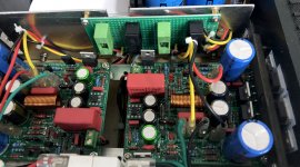
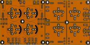
I see you have two diode rectifiers in parallel. This will increase noise and I highly recommend do not do so. Use a sigle pair or diode or make use of synchronous rectifiers.
I know that I already mentioned synchronous rectifiers several times by now, but the effort to use them make a huge difference.
Regards,
Tibi
Hello Tibi,
I only have this board that fits in my box. It works well. I have used it for other projects without particular concern. For the noise of the double diode bridge, I do not hear the difference. Maybe with the scope?
I don't know if we can remove one of the bridges for each supply rail. Here is the PCB in close-up front and back.
By ear with my small broadband HP which serves as a "headphone", the background noise (like white noise) is less important with this power supply than with the SMPS power supply. On the other hand, I hear a very slight noise of 50Hz residue that I do not have with the SMPS. It is practically inaudible with speakers (ear glued to the speaker). I have not yet redone the measurements with the final config in the box.
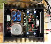
I spent the amp on my pair of JBL L75 Minuet. The sound is very pleasant. Not at all aggressive but dynamic. A lot of grain with the voices, which is pleasant. A little less than its a class A anyway. With the Jennings Contrara which have a lot of bass, I see that the bass sounds very well mastered. Neither too dry or dragging. When the amp has been running for several days, I would try it out on my Dynaudio Contour 3.4 to see how the amp behaves with low efficiency, 4R, and twisted filter speakers.
The 160VA transformer seems quite sufficient for normal HIFI listening.
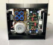
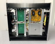
A few more pictures of the amp.
Good Sunday,
Stef.
.
I only have this board that fits in my box. It works well. I have used it for other projects without particular concern. For the noise of the double diode bridge, I do not hear the difference. Maybe with the scope?
I don't know if we can remove one of the bridges for each supply rail. Here is the PCB in close-up front and back.
By ear with my small broadband HP which serves as a "headphone", the background noise (like white noise) is less important with this power supply than with the SMPS power supply. On the other hand, I hear a very slight noise of 50Hz residue that I do not have with the SMPS. It is practically inaudible with speakers (ear glued to the speaker). I have not yet redone the measurements with the final config in the box.
I spent the amp on my pair of JBL L75 Minuet. The sound is very pleasant. Not at all aggressive but dynamic. A lot of grain with the voices, which is pleasant. A little less than its a class A anyway. With the Jennings Contrara which have a lot of bass, I see that the bass sounds very well mastered. Neither too dry or dragging. When the amp has been running for several days, I would try it out on my Dynaudio Contour 3.4 to see how the amp behaves with low efficiency, 4R, and twisted filter speakers.
The 160VA transformer seems quite sufficient for normal HIFI listening.
A few more pictures of the amp.
Good Sunday,
Stef.
.
Attachments
Last edited:
Hello,
I hadn't been paying attention but I just noticed that the input sensibility of Q17 is too strong. It seems designed for an old school input sensitivity of 0.5V (or 0.75V RMS, not sure) while modern equipment is in 1.5v RMS. It goes badly with my others equipments. I have to lower the gain everywhere and redo my settings otherwise it saturates.
How to fix all this?
Stef.
Having an amplifier with 0.75Vrms sensibility is not an issue. A good attenuator, with enough steps, may be a solution. IMHO, the problem is when you have an amplifier with low gain and low sensibility and you start to look for preamplifiers.
However, by lowering R18 you may change the gain of the opamp to the value you want.
Regards,
Tibi
However, by lowering R18 you may change the gain of the opamp to the value you want.
Regards,
Tibi
HI Tibi,
Found in the documentation:
As I am very bad at math, what are the values for a sensitivity of 1.5V RMS?
I also found this explanation on this QUAD405 page:
https://www.desmith.net/NMdS/Electronics/QUAD_upgrades.html#gain
Stef.
Found in the documentation:
R17 and R18 are part of operational negative reaction will set the gain to (R17+R18)/R17=7,6.
As I am very bad at math, what are the values for a sensitivity of 1.5V RMS?
I also found this explanation on this QUAD405 page:
https://www.desmith.net/NMdS/Electronics/QUAD_upgrades.html#gain
Gain Reduction
The ratio of R6 to R3 defines the input stage gain - Originally this was 330K/22K = x15 (+23.5dB) - now changed to 100K/22K = x4.6 (+13.2dB)
The class-A stage has a gain of 3.78 - this is determined by the potential divider formed by (R20||R21) & R16, i.e. (180+500)/180 = 3.78 so the overall gain was originally 15x3.78 = 56.7 (+35dB) and after reduction is 4.6x3.78 = 17.39 (+24.8dB).
Reducing gain by a factor of approximately 3 (15/4.6) reduces input sensitivity for full output from 0.5V RMS to 1.5V RMS which is in keeping with most modern equipment
Note that by reducing the front-end gain to 4.6 rather than 5 reduces the power output (into 8 ohms) from 100WRMS to a theoretical 85WRMS. It might seem a bigger drop than you would expect, but remember that power depends on the square of the voltage gain - to get a full 100WRMS you will actiually need 1.63VRMS of input.
Stef.
- Home
- Amplifiers
- Solid State
- Q17 - an audiophile approach to perfect sound