1N5819
Others are too big (TO220).
https://www.mouser.fr/ProductDetail...N5819-TR-TIN-LEAD?qs=l7cgNqFNU1irnqT5NmOjgg==
I would take some the next time I order components.
I am comparing BD135 and BD139 for Q12.
Stef.
Others are too big (TO220).
https://www.mouser.fr/ProductDetail...N5819-TR-TIN-LEAD?qs=l7cgNqFNU1irnqT5NmOjgg==
I would take some the next time I order components.
I am comparing BD135 and BD139 for Q12.
Stef.
Last edited:
More on this.
Amusing. With the new fresh Q4, I now have 14.30v on the positive rail and 14.31v on the negative rail. Measures taken after half an hour. 39mV at output (was 41mV). The influence of the symmetrical voltage is very weak on the output offset. JI'm not sure if I paced the zener back in the same place. So another influence on the circuit. I also replaced the BD135 that I was using on Q12 with a BD139. I don't know if that can have an influence. At first glance, no difference but I do not know the protocol to evaluate this component at this position. The BD139 is better "physically". It has a metal side. It is therefore easier to set up than the BD135 which is all plastic. Harder to make a pinout mistake.
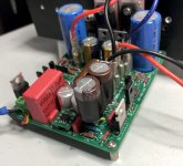
The PCB from JLCPCB is of good quality. In some places, I have desoldered five or six times. No broken pellet.
Stef.
Amusing. With the new fresh Q4, I now have 14.30v on the positive rail and 14.31v on the negative rail. Measures taken after half an hour. 39mV at output (was 41mV). The influence of the symmetrical voltage is very weak on the output offset. JI'm not sure if I paced the zener back in the same place. So another influence on the circuit. I also replaced the BD135 that I was using on Q12 with a BD139. I don't know if that can have an influence. At first glance, no difference but I do not know the protocol to evaluate this component at this position. The BD139 is better "physically". It has a metal side. It is therefore easier to set up than the BD135 which is all plastic. Harder to make a pinout mistake.
The PCB from JLCPCB is of good quality. In some places, I have desoldered five or six times. No broken pellet.
Stef.
Last edited:
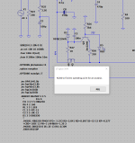
I'm a beginnerTo properly run Q17 simulations, several libraries must be included into project.
These are proprietary, but can be downloaded from:
OPA1641 ->https://www.ti.com/lit/zip/sbom627 unzip and extract OPA1641.LIB
FQA36P15 -> https://www.onsemi.com/pub/collateral/fqa36p15.lib
FQA46N15 -> https://www.onsemi.com/pub/collateral/fqa46n15.lib
FQP3N30 -> onsemi
FQP3P20 -> onsemi
Download these and place in the same directory with Q17 ltspice asc file. Open simulation file with ltspice and include following spice directives:
.inc OPA1641.LIB
.inc fqa36p15.lib
.inc fqa46n15.lib
.inc fqp3n30.lib
.inc fqp3p20.lib
To run transient, uncomment ;.tran 0 200m 100m 10m
Regards,
Tibi
Failed to find DC operating point for AC analysis.
Attachments
Stef, you are on the wrong track regarding the output offset voltage of the opamp. The effect of the symmetrical power supply is minimal. You should match the DC impedances of the opamp's positive and negative inputs. A mismatch will result in a DC offset.
Hi Piersma,
Sorry but I've not understood:
Trying -++- 2x220uF Silmic on C2. No output offset change or something else on the scope's curves. I'll leave them for now. I will try later if I hear a difference.
Stef.
Sorry but I've not understood:
You should match the DC impedances of the opamp's positive and negative inputs
Trying -++- 2x220uF Silmic on C2. No output offset change or something else on the scope's curves. I'll leave them for now. I will try later if I hear a difference.
Stef.
Attachments
Hello,
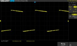
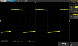
Some tests with different capacitors for C2, C3 and C6.
Frequency: 40Hz
Input: 23mVRMS, output: 1.12vRMS
First picture (standard config):
C3, C6 = 100uF/25v, C6 = 100uF / 16v BP Muse:
Offset: 41mV
Second picture:
C3, C6 = RFS 10uF/16v, C6 = 100uF / 16v BP Muse:
Offset: 41mV
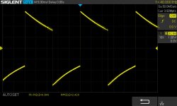
Third pictures:
C3, C6 = RFS 10uF/16v, C6 = 2x100uF / 6.3v RFS:
Offset: 42mV
You can easily see the influence on the signal. We can't see very well on the pictures but with 10uF in C3 / C6, there is noise around the square signal.
Stef.
Some tests with different capacitors for C2, C3 and C6.
Frequency: 40Hz
Input: 23mVRMS, output: 1.12vRMS
First picture (standard config):
C3, C6 = 100uF/25v, C6 = 100uF / 16v BP Muse:
Offset: 41mV
Second picture:
C3, C6 = RFS 10uF/16v, C6 = 100uF / 16v BP Muse:
Offset: 41mV
Third pictures:
C3, C6 = RFS 10uF/16v, C6 = 2x100uF / 6.3v RFS:
Offset: 42mV
You can easily see the influence on the signal. We can't see very well on the pictures but with 10uF in C3 / C6, there is noise around the square signal.
Stef.
Attachments

Hello Stef,
I ordered Panasonic FR 330 uF /25V for my latest setup for C3/C6, they are small and very good for current stabilisation.
For C4 / C5 I overdid it as usual and installed both 100nF MKP and the 33nF FKP.
Regards Tim
I ordered Panasonic FR 330 uF /25V for my latest setup for C3/C6, they are small and very good for current stabilisation.
For C4 / C5 I overdid it as usual and installed both 100nF MKP and the 33nF FKP.
Regards Tim
Last edited:
Thank you very much for your measurements, Stef !
May I suggest you to use a linear power supply.
Q17 was designed to rely on a good active power supply which I highly recommend. Files are on github.
Regards,
Tibi
May I suggest you to use a linear power supply.
Q17 was designed to rely on a good active power supply which I highly recommend. Files are on github.
Regards,
Tibi
Hello!
For Tim: I tried with more that 100uF (FC 220uF) for C3 & C5. No change on scope.
For Tiby: If you want a new measure with something else in C2, tell me. Currently, the best is still 100uF Muse BP. We only see a difference for the low frequencies.
I still looking to found a method to reduce output offset. Can we play with R17 and/or R18?
Cheers,
Stef.
Stef,
You may play with R17 and R18 to reduce output offset, but 40mV is not something to focus on.
Personally, I would focus on smps noise, that clearly affect amplifier performance and this is seen in your measurements.
Regards,
Tibi
You may play with R17 and R18 to reduce output offset, but 40mV is not something to focus on.
Personally, I would focus on smps noise, that clearly affect amplifier performance and this is seen in your measurements.
Regards,
Tibi
Yes, it's noisy but at the moment I only have that. We can see the bumps on the REW / RTA at -80dB BUT I can hear it on my test broadband speaker. With the same speaker, my Pass AM 15W with the big analog PSU produce no noise. We can't say if the amp is on or off. We still have to put things into perspective. Noise can only be heard with the ear glued to the speaker.
For C2?
It seems that what we put in C2, there is a big difference on frequencies below 200 Hz, at least on the square signal. Which will automatically change the sound signature of the Q17. With my old ears, it's more difficult and above all very subjective.
Stef.
EDIT:
I forgot to specify that currently the Q17 proto is connected with a 60cm electric cable to the power supply which is in the chassis of my old Chinese Quad405. This is not the best. 😉
Last edited:
Hello Stef,
you have two FC 220uF, these two as C2, I think that sounds warmer than the very clean playing Muse BP. that would be another experiment for you.
Tim
you have two FC 220uF, these two as C2, I think that sounds warmer than the very clean playing Muse BP. that would be another experiment for you.
Tim
The DC offset should be minimal if you match the input impendance. Try R16 = 13 k.Hello!
For Tim: I tried with more that 100uF (FC 220uF) for C3 & C5. No change on scope.
For Tiby: If you want a new measure with something else in C2, tell me. Currently, the best is still 100uF Muse BP. We only see a difference for the low frequencies.
I still looking to found a method to reduce output offset. Can we play with R17 and/or R18?
Cheers,
Stef.
Hello!
More C2 test with 2x220uF.
I mounted C2 on a tulip socket. It is faster.
Tested Panasonic FC, Vishay BC 150 and Elna Silmic II. See name of the picture.
The FC is the worst (on the scope as well).
I have the impression that the bigger the capacitor is physically the better it is.
Stéphane
More C2 test with 2x220uF.
I mounted C2 on a tulip socket. It is faster.
Tested Panasonic FC, Vishay BC 150 and Elna Silmic II. See name of the picture.
The FC is the worst (on the scope as well).
I have the impression that the bigger the capacitor is physically the better it is.
Stéphane
Attachments


Is not an impression. Physically bigger electrolytic capacacitors sound better....
I have the impression that the bigger the capacitor is physically the better it is.
...
Regards,
Tibi
It is obvious with the Silmic. The 220uF 6.3v (D5) is very very bad and the 25v (D12.5) version is ok.
And with a film capacitor?
https://www.ebay.fr/itm/152319027409?hash=item2376ebe8d1:g:6OYAAOSwo4pYKx3T
Stef.
And with a film capacitor?
https://www.ebay.fr/itm/152319027409?hash=item2376ebe8d1:g:6OYAAOSwo4pYKx3T
Stef.
Last edited:
Guy's, does C2 have to be a low esr Cap or regular ?It is obvious with the Silmic. The 220uF 6.3v (D5) is very very bad and the 25v (D12.5) version is ok.
And with a film capacitor?
https://www.ebay.fr/itm/152319027409?hash=item2376ebe8d1:g:6OYAAOSwo4pYKx3T
Stef.
- Home
- Amplifiers
- Solid State
- Q17 - an audiophile approach to perfect sound