Stef,
Before adding 1uF between Q15/Q16 and Q17/Q18, I suggest you to listen the amplifier in stereo. I mean to give a serious listening session, at least few hours.
Than add that capacitor and listen again.
You may simulate and measure first, but what I suggest is that any modification you made from original Q17 to be based on a serious listen.
Trust your ears.
Regards,
Tibi
Hi!
Problem after changing R29/R30 to 10K (was 10R by mistake).
I've a big sound when I switch on the board (no speaker protection with delay).
https://voca.ro/14lPmzbkjBWY
No sound before. After that, the board seems to play fine.
Stef.
Problem after changing R29/R30 to 10K (was 10R by mistake).
I've a big sound when I switch on the board (no speaker protection with delay).
https://voca.ro/14lPmzbkjBWY
No sound before. After that, the board seems to play fine.
Stef.
Is it the power supply that starts or the amplifier board that stabilizes?
I tried again with 10R. I have a very weak and low frequency sound anyway. Bandwidth?
In real life, I would have an HP delay / protection module, but I'm not sure its delay is long enough.
Stef.
I tried again with 10R. I have a very weak and low frequency sound anyway. Bandwidth?
In real life, I would have an HP delay / protection module, but I'm not sure its delay is long enough.
Stef.
Hello Tibi,
there is still something I don't understand yet, that is the work of Q13 in running operation - the start is understandable so far.
The following: for an unknown reason on some boards of my setups Q13 does not start (this happens one day), consequently there is no power supply on the positive ower rail - the LEDs of the positive side do not turn on.
When I measured the non-functioning Q13 MOSFETs (which still work normally and which I then use as voltage regulators), I always had very low internal resistances (< 1 Ohm, max. 1.1 Ohm). The Q14 has internal resistances from more than 1.9 ohms. Therefore, I have now installed IRF610 with Rgs > 1.5 Ohm in the new set-ups for Q13, in the hope (since I have not yet understood the capacitance booster, which is the correct name for this circuit isn't it?) that Q13 will then work reliably.
What I see in the simulation is that when I put R32 in the model, the simulation gives a stable result up to about 5 ohms. The differences in Q13 and Q14, which are replaced by resistors in the simulation, also destabilise the simulation and lead to it not finding a DC operating point.
Now there is the analysis of the + power rail, which needs a capacitance of 2200uF in the simulation, so that it doesn't play much - i.e. has a low level. I understand that in the real Q17, this calming of the voltage should be done by the Q13, i.e. that load variations are damped by the regulation of Q13 against C13, or is that wrong?
In the amplifier, which plays excellently, C13 and C14 are 330uF (they were just left over).
Regards Tim
Last edited:
Ok, go for 1k. Should be ok.
Regards,
Tibi
Much less noisy but still there (shorter and lower). The the delay in the protection module is longer than the board startup. So no worries.
Thanks.
Stef.
Hello Tim,
The role of Q13 and Q14 is to act as capacitor multiplier, but in the same time to allow a soft start.
At very first start, Q13 source is a low potential and transistor start to conduct when Vgs become positive at ~3V.
When transistor is on, internal Rdson become lower and shunt the resistor.
If you do not want to use Q13 and Q14, remove them make R29/R30=10 ohm and connect gate to source.
Regards,
Tibi
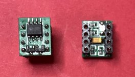
What is the role of that circuit ?...
OPA1611A with a circuit on the socket.
...
I see no reason that Q17 do not work with a very large number of opamps.
Regards,
Tibi
I have this in the Chinese QUAD405 for years. It works and the small red led below illuminates the PCB and components around. It’s fun.
Stef.
https://www.ebay.com/itm/253841765707
Stef.
https://www.ebay.com/itm/253841765707
The general amplifier NE5532 OPA2604 output current less than 50MA, OPA1611 + A class after the expansion of output up to 200MA, greatly increased the driving force, the circuit has a better match, lower output impedance, high and low level, dynamic So the performance is very good.
This product on the basis of 1611, add 1 pair of NPN PNP complementary symmetrical 500MA current level Philips low noise tube, so that the output capacity increased by 4 times, and run in the state of class A, the sound quality is very full and delicate and warm.
Transparent, analytical power is very good, open sound field, better than OPA604
OPA1611 (Single Channel) Bipolar Input Operational Amplifier achieves very low noise density at 1kHz
(1.1nV/√Hz) and ultra-low distortion (0.000015%). The OPA1611 and OPA1612 are capable of providing rail-to-rail output in the range of 600mV from the supply rail at 16-600 ohms load, which helps to maximize dynamic range.
These devices support a wide supply voltage range of ± 2.25V to ± 18V, with only 3.6mA per channel supply current. The OPA1611 op amp's unity gain is stable and maintains excellent dynamic performance over a wide range of load conditions.
Last edited:
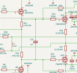
I took another look at the Github Q17 schematic. Your bipolar capacitor C2/A is faulty connected. Short both negatives (or positives.)
Lower C3 and C6 to 10 uF
Lower C3 and C6 to 10 uF
Why with such a large capacity?Just bypass R11 and R12 with only one 1uF capacitor. Connecting the gates of Q15 and Q16
Couldn't 1nF be enough?
I took another look at the Github Q17 schematic. Your bipolar capacitor C2/A is faulty connected. Short both negatives (or positives.)
Lower C3 and C6 to 10 uF
Hi!
Modified on GitHub.
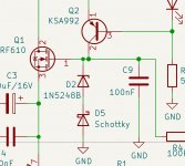
I tried with a 5K trimmer instead of Zener D2 and D3. I preset trimmers to 3K75 and turned on without opamp. I got around 12V on each rail but something it's broken somewhere now. The R27 was hot and I got -43v at speaker output.
I put the zeners back on and I still have -43v now. I have to find what broke.
The joys of testing ...
I have not tried with schottky diodes. I did not find any small schottky diodes in my stock, only large 10A ones.
Have a nice day.
Stef.
Is not a good thing to power the amplifier without opamp, because Q7 base will float. If you want to do so, please add across C1 a resistor - anything between 1K and 100K should be ok. Than remove opamp and make the tests.
Regards,
Tibi
Regards,
Tibi
It started with a good feeling. I didn't want to burn U1. 😉
Q4 9610 dead. Soldered a new one.
Controled Q1, Q8, Q5, Q6, Q12. They are OK
D2 and D3 ok.
Still -43v.
Next?
Stef.
Q4 9610 dead. Soldered a new one.
Controled Q1, Q8, Q5, Q6, Q12. They are OK
D2 and D3 ok.
Still -43v.
Next?
Stef.
Q7 is OK. The amp is back with an opamp socketed. 40mV at output.
Result of my test: Q4 burnt.
My opinion. This modification is dangerous because it burns without opamp, therefore complicated to adjust the voltages of the opamp. and if you insist, other components will burn too due to heating.
I'm going to search my boxes again for small schottkys. If I can't find what type of schottky would be good for testing?
Stef.
- Home
- Amplifiers
- Solid State
- Q17 - an audiophile approach to perfect sound