I used the search filters of Mouser to find an alternative to FQP3N30 and come up with the following MOSFET: FDU3N40TUHello,
We have a problem, the FQP3N30 is disappearing. Stocks are running out everywhere (there are no more at Mouser, for example).
Do we have an alternative?
Stef.
It also has very low capacitance and the given diagrams seem similar at first. This is also available in SMD design: FDD3N40TM
For laterals, R14 and R14 should be increased as well to 510 ohm respectively 390ohm.
P2 with +/-58V may reach ~200W/8ohm.
Regards,
Tibi
P2 with +/-58V may reach ~200W/8ohm.
Regards,
Tibi
Hi Tibi,
"R14 and R14" ???
Currently we have 330R for R14 and R15.
I take a look to the EXICONs. It is really very expensive. 120€ for 8 transistors !!!
Stéphane
"R14 and R14" ???
Currently we have 330R for R14 and R15.
I take a look to the EXICONs. It is really very expensive. 120€ for 8 transistors !!!
Stéphane
Happy birthday !!
One more. For R14 and R15, 510R or 390R with Exicon? The sentence is not very clear.
Warning with FQP3P20 (P-Channel). Of the seven units I ordered from Farnell, two were DOA and I found out two more have Rds of 0.39K !!! (around 5R for the others).
Stef.
EDIT: I was talking of the P-Channel FQP3P20 not N-Channel FQP3N30.
Last edited:
Hello Tibi,
I am trying to evaluate my results from the experiments with the Q17 and the MosFET voltage control from you and optimise the Q17 from the findings.
One important point that contributes to the fact that your Q17 plays beautifully is R32. I tried out what a preamplifier based on OPA1656 does when you put a resistor like this in the ground between the rectifier and the filter capacitors. It sounds very old scool, i.e. it plays echoes, which is also what the 3-fold Q17 did. That's why I changed the ground assignment and added a separate power connection for the OP.
The objective is that the impedance of the input GND becomes lower, as it is now stabilised via the OP's power supply.
The driver stage of the Q17 no longer influences the input GND, but is routed to the power GND, which should make the amplifier even more precise - which then does not always sound advantageous (more precision quickly reveals deficiencies of the source or speakers).
This is an experimental basis and not an airy and nice sounding setup like the original circuit!
Have you already connected previous Q17s to the power GND in a similar way?
The question is, how high can the acoustic imaging performance be increased? My last attempt shows potential, so I didn't throw out the C-Q5 and C-Q6, just reduced them to a minimum.
Regards Tim
Attachments
Happy birthday !!
One more. For R14 and R15, 510R or 390R with Exicon? The sentence is not very clear.
Warning with FQP3P20 (P-Channel). Of the seven units I ordered from Farnell, two were DOA and I found out two more have Rds of 0.39K !!! (around 5R for the others).
Stef.
EDIT: I was talking of the P-Channel FQP3P20 not N-Channel FQP3N30.
R14 = 510ohm and R15 = 390ohm for ECW20N20 and ECW20P20
Regards,
Tibi
Tim,
R32 is there to separate signal gnd from powergnd. This is to avoid noise from high current dumpers to pollute small signal.
Q17 have exceptional soundstage and 3D imaging.
I suggest you to follow my original schematic. You have added parts that degrade amplifier performance. Therefore, please remove my name from the drawn schematic, or change on "Schematic by Tim based on Q17 by Tiberiu Vicol".
Thank you !
Regards,
Tibi
Hello Tibi,
I think your circuit is great, otherwise I wouldn't have been experimenting with it for a good half year.
There is no question that your original circuit sounds great, plays a great stage and sets standards in both low bass and treble.
The basic idea of installing the ground resistor is also understandable. Since this insert does not always work without limitations and I was concerned about feedback via GND, I think it makes sense for a discussion and also a test to connect the components C1 and R6 alternatively to Power GND and Input GND.
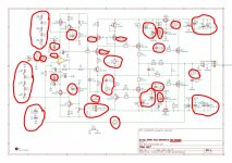
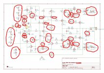
I have now marked everything in the circuit diagram that I have changed, admittedly it is quite a lot.
Regards Tim
I think your circuit is great, otherwise I wouldn't have been experimenting with it for a good half year.
There is no question that your original circuit sounds great, plays a great stage and sets standards in both low bass and treble.
The basic idea of installing the ground resistor is also understandable. Since this insert does not always work without limitations and I was concerned about feedback via GND, I think it makes sense for a discussion and also a test to connect the components C1 and R6 alternatively to Power GND and Input GND.
I have now marked everything in the circuit diagram that I have changed, admittedly it is quite a lot.
Regards Tim
Attachments
Last edited:
Hello,
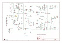
Just to tell you that I loaded on the GitHub a new version of the diagram for the Q17-Mini (resistor values for the Exicon ECW20N20 and ECW20P20) and a new version of the Q17-P2 (some mods on the silkscreen of the PCB and more manufacturer part numbers for the components).
https://github.com/stefaweb/Q17-a-QUAD405-audiophile-approach
Have a nice week end,
Stef.
Hello Stef,
do you plan to build up a Q17 with double Exicon ECW20? That is undoubtedly a very good comparison to your small QUAD design.
I will wait with interest for your reports about it.
Regards Tim
do you plan to build up a Q17 with double Exicon ECW20? That is undoubtedly a very good comparison to your small QUAD design.
I will wait with interest for your reports about it.
Regards Tim
Hi Tim,
I don't have the budget to build a P2. I also don't really need all that power. I already have a powerful amp for my Dynaudio 3.4 (a Burmester 956 clone) that I built a few months ago.
Just for the Exicon, there is some for 120€ and even if I do not take any spare transistor. For two boards, I think you need a component budget of 350/400€. Then add the cost of a big PSU and nice cabinet.
Ultimately, I can build two boards for someone to see how they work.
Stef.
Hello Stef,
that's great that you can now make a real step up with the Q17 Quad and give your 956 Clone to friends.
The Q17 can play your Dynaudio 3.4 to their limits, at least it has already done so with larger speakers.
It is not necessary to build a P2 for hi-fi loudspeakers, the interesting thing is to control PA subwoofers, because they can handle even more power than a pair of FQA are able to deliver.
Regards Tim
I took 10 years and built 4 amps to find an amp that awakens the Contours. I'm not at all ready to sell the Burmester. 🙂
On the other hand, I am going to remake a prototype (I haven't had any since I stripped it to make my two final boards) with the P2 PCB to tinker with and do tests.
Stef.
On the other hand, I am going to remake a prototype (I haven't had any since I stripped it to make my two final boards) with the P2 PCB to tinker with and do tests.
Stef.
Tim,I have adjusted more capacitor values. I also use a different capacitor quality than Tibi.
First, I want to say that your contribution to the project is greatly appreciated.
Second, you did many modifications, so will take me a lot of time to comment each of them.
I'll try to be short.
- R1n1 = 10K depending on your potentiometer, this will get an extra 10K in series opamp Vin+. I know you want to achieve same impedance on In+ and In-, but IMHO this is not a good solution.
- D2...D14 - using multiple led's in series with Zener's will have far higher noise than a single Zener. Even several led's in series have higher noise than a single Zener.
- C8 and C9 must decouple the component you intend too. I mean the capacitor must be close to that component.
- C27 & R22. These should not be there, Will affect amplifier bw and operation. Are in negative reaction path and will increase gain at high frequency, making amplifier to oscillate.
- C17 and C2. Why you should use two bipolar in series ? Use one good bipolar Nichicon MUSE, or two polarised Panasonic FC in series.
- C5 and C6 will increase capacitance seen by class A stage and , as you placed, may generate oscillations as well. Final stage have enough input capacitance, there is no need to increase this even more. If you want to slow down class A stage, the best way is to increase gate stoppers, or move C5 and C6 on each transistor between gate and drain.
- moving powergnd in Q7-R6 is debatable. It may highly depend on the PCB layout
- R31 is probably the best modification that can be made. Zobel network must be matched with the speaker you use.
Q17 is open source and anyone can modify, alter and build the amplifier as they like, but when you make your project public, please state clearly what modifications you have made. If you can justify why these are in place, it will be much appreciated, so , on my turn, I may improve this design further.
Regards,
Tibi
[*]C17 and C2. Why you should use two bipolar in series ? Use one good bipolar Nichicon MUSE, or two polarised Panasonic FC in series.
Hello,
My tests show that a single Muse BP is better in scope than two Panasonic FCs here (Especially with frequencies below 100Hz). I plan to redo tests for C2 with more brand capacitors by comparing the result in the scope and their impact on the DC offset output.
Have a good Sunday.
Stef.
Hello Tibi,
Thank you for your comments.
I will summarise my findings here:
1. the layout of the PCB has an influence on the amplifier, my variant 4 is thereby also silent with the ear on the speaker, the last one has a smacking noise when no music signal arrives.
2. at the first setup I installed a MKP as C7, this one doesn't sound fine in the tweeter, so I installed a KP tin foil, after that the amplifier clattered. Since I played with the simulation in advance to find a solution without L1, I found out that with the link of C27 and R22 the amplifier plays with strongly reduced induction in the simulation. The main difference between an MKP and a KP tin is in the high frequency range, where the KP tin still works very undamped, the MKP has increased error angles here (inductive and ohmic resistances). A gold-silver oil also has these errors in the high-frequency range, so I can understand why you achieve an excellent result with it. My test: adding C27 and R22 made the amplifier play clean even with the KPSN.
3. I have increased the capacitances for voltage stabilisation, adding C13 and C14 several times as 220uF/63 Panasonic FC or Europe Chemi-Con LXZ (these measure much worse than the Panasonic, but lead to a very dynamic bass - which is not ultra clean) and because of component availability also 330uF/50V Panasonic FC in model no.4. I like this result best, so I have currently added this again. In the simulation model you can see that the + rail of the driver stage oscillates quite a bit depending on the capacitor. This will undoubtedly not occur in the real setup, as Q13 and Q14 stabilise the voltage. Since some IRF610s don't start with 10k, I reduced R29 to 8.2k, and so far all Q17s start.
I have listened through some capacitors for C2. Two Panasonic FC play a dynamic bass without overdriving, one 100 uF Muse plays balanced neutral and two 220 uF Muse in series play super precise. I love this, as percussion is reproduced with a realistic imaging quality I have never heard before. In these experiments I also lowered R23 to 8k, so for practical reasons I use 8.2k resistors. With this I get a maximum realistic sound image.
With these measures my amplifier No. 4 and No. 7 are built up and both are characterised by extraordinarily precise bass performance with unbelievable low bass, which usual amplifiers cannot play in such a way - at least no comparison amplifier, no matter what power and price class, could do that so far. These amplifiers exhibit extraordinary airiness, even though the tweeters of the speakers are not ribbons, which is also very impressive. The acoustic stage in its 3d imaging and the naturalness of the voices also sets standards.
What is very extraordinary is that this amplifier sounds very good on cheap DAC as well as on excessively elaborate and precisely playing DAC and so far draws a smile on the face of all listeners.
Now to further modifications:
I have no measurement basis for the noise of Zener diodes. My knowledge is that LEDs are quite low-noise and very precise, and actually provide very precise voltage stabilisation. I've also used 3x 6.2V Zener diodes and didn't get an audibly different result, so I don't have any results from tests here.
For Dali Epicon 8 I'm currently building Q17 No. 9, which should play more dynamically than Q17 No. 4 and No. 7 described above, so I want to stabilise the voltage on the power side with Europe Chemi-Con LXZ, even after rectification. I also set up C2 with two Panasonic FC with opposite polarity. The Epicon 8 are not such precise playing speakers, the crossovers of these speakers are already tuned, as this improves the sound by classes, also the exchange of the damping material. This makes the Epicon 8 sound more relaxed, they can be listened to for a long time and they play much more freely. Since the speakers are in a roof space, the bass sounds rather dry and the bass could be given more substance. Now, since the Epicon 8's can't play bass super precisely, there is no requirement to trim the amp for bass precision, but rather for bass volume - which is a very subtle reverberation - so increasing the Q above 0.5.
I tried to trim amplifier no. 8 to max. precision, this has a very small transformer, because the amplifier has to play the power range of 1W perfectly and no level orgies. Here, the bass is super dry precise (2200 uF/63V at the FQA) due to inexpensive cup electrolytic capacitors Samwha Series: HC and the treble is slowed down by the capacitors C-Q (470pF at this amplifier). This makes recordings like Gregory Porter - Liquid Spirit sound even cleaned up and the instruments are more clearly delineated from each other. According to my observations, such an amplifier is no longer "generally" suitable, as it is more suitable as an amplifier for monitoring. Compared to amplifiers No. 4 and No. 7, No. 8 is ultra analytical and less emotional. In this amplifier I also increased C3 + C6 to 330uF / 25V and added 100nF MKP2 to the 33nF FKP2. And yes, the traces between the current pins of the OP and the capacitors are very short.
C-Q is a capacitor that is not installed between the source and drain of the FQP as everyone would do, but between the source and +. Note here that the capacitance of the power transistors are biased against the output, ultimately against PWRGND. My idea is twofold: 1. with the C-Q I can damp the amplifier above 100 kHz - this is advantageous, secondly I can damp the polarity reversal pulses of the FQP. Here's an experiment: I set up the Q17 No. 6 with three power pairs and it played echo effects, as always depending on C7 (with the KPSN these were loudest). With C-Q = 2.2nF these echo effects disappeared completely.
With Q17 No. 8 I did some experiments, here I also reduced R32 to 5 Ohm. The DC offset dropped from 42mV to 27mV. Considering the fact that a constant current flows through R6, it is clear that the input GND must have a positive potential of less mV relative to the power GND. If you simulate Q17 with R32, you will see that the effectiveness of C1 is influenced via R32. As you write, this is related to the board layout. I notice that the shorter the tracks, the more noise the amplifier produces. This is not fundamentally illogical, but it also leads to the thesis that it can make sense to put C1 and R6 on Power GND. Therefore, I have redrawn a layout in such a way that I put C1 and R6 on one track and have a bridge to be able to switch between Input GND and Power GND.
Now some findings from amplifiers No. 3, No. 5 and No. 6.
No. 3 was a setup with paired double FQA (without source resistance), which so far played the cracking bass on my 12 inch Oberton subwoofer drivers. However, with deficits in the high frequencies, relative to the single FQA models.
No. 5 was the setup with bridge mode, where I could compare the OPA1612, OPA1642 and OPA1656. This one played great when cold, with warm up very quiet echo effects started. I did not test this one further, not even at higher volume, no idea how loud this one can play.
No. 6 is largely built with the components of No. 5 and played much louder echoes, which disappeared with the installation of the 2.2nF. I compared this one with Q17 No. 4. Here No. 6 totally fails as it lacks bass control - I put this down to the fitting of the source resistors to the FQA and, like No. 3, it plays a not so clean treble. So it is a step backwards from the Q17 single model. These experiments also explain why the Exicon play softer when they can be installed without source resistors. The Exicon as internal multiple transistors cannot play with the precision of an FQA, but are easier to use in an amplifier.
What is my conclusion: the Q17 sets new standards for poweramplifieres.
Modifying the Q17 is exceptionally tricky, so using the original layout makes perfect sense.
My next step is to build a Q17 with its own power supply for the OPA. I realise that this does not have any advantages at first, as the starting behaviour is not exactly easier either. However, since I can easily apply very clean current in the input sector with this additional power supply, I expect the OPA to find ideal working conditions.
I want to optimise the following:
the current through R32, this should tend towards zero.
This leads to the following considerations:
the correction circuit of the driver stage is currently working against the input GND and can thus orient itself to the input signal without errors, shifted by the DC error that results from the current through R32 (precisely from the voltage drop at R32).
If R6 and C1 are connected to Power GND, then this circuit is oriented to the ground of the speakers, so the DC offset should tend towards zero. If there is too much noise in the Power GND, it can be assumed that the imaging quality will suffer. Therefore, it should be tested to what extent the routing of R6 and C1 to the Power GND is advantageous.
That's where I stand.
Regards Tim
Hello Tim,
With some of your statements I agree. 🙂
What else can be improved ?
Regards,
Tibi
With some of your statements I agree. 🙂
What else can be improved ?
- as you mentioned, separate power supply for opamp may be an improvement.
- add gate stoppers to Q1 and Q4. 10ohm may be enough
- move C7 with negative foil at the opamp output
- decoupling led D1 and D4 with a ceramic 100nF
- change Q12 with a n-chanel mosfet . This will require R10 and R13 to be increased to ~50ohm - 60ohm, therefore the gain of Cass A stage decrease, but will become more linear. Current dumping operation will be affected a bit, due Class A stage require gain as high as possible. Here is a light balance I have not tested yet. You may give it a try.
- - Zobel network. Adjust R31 per speaker.
Regards,
Tibi
Hi Tibi and Tim,
C7 move is done here on both Mini and P2.
For R31, do you have the value for 4R speaker?
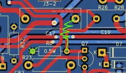
Try R6 on GNDPWR ground will be easy to test with the P2 PCB if you want. See picture. Possible with C1 (but at first I don't see the advantage).
Others tests as LED decoupling or gate stoppers for Q1 and Q4 can also be done very easily.
For gate stoppers, I thought 47R was the minimum?
Stef.
C7 move is done here on both Mini and P2.
For R31, do you have the value for 4R speaker?
Try R6 on GNDPWR ground will be easy to test with the P2 PCB if you want. See picture. Possible with C1 (but at first I don't see the advantage).
Others tests as LED decoupling or gate stoppers for Q1 and Q4 can also be done very easily.
For gate stoppers, I thought 47R was the minimum?
Stef.
Attachments
Last edited:
- Home
- Amplifiers
- Solid State
- Q17 - an audiophile approach to perfect sound