C2 must be bipolar. Not low ESR.
Please use parts listed in my BOM
https://ro.mouser.com/ProductDetail/Nichicon/UES1C101MPM1TD?qs=JgOBn5pVFoqelxyCFlUB6Q==
Regards,
Tibi
Please use parts listed in my BOM
https://ro.mouser.com/ProductDetail/Nichicon/UES1C101MPM1TD?qs=JgOBn5pVFoqelxyCFlUB6Q==
Regards,
Tibi
Thanks Tibi.C2 must be bipolar. Not low ESR.
Please use parts listed in my BOM
https://ro.mouser.com/ProductDetail/Nichicon/UES1C101MPM1TD?qs=JgOBn5pVFoqelxyCFlUB6Q==
Regards,
Tibi
Hello!
I've received the production Q17-Mini boards.
I will contact the people who requested me tomorrow.
Have a good evening,
Stef.
I've received the production Q17-Mini boards.
I will contact the people who requested me tomorrow.
Have a good evening,
Stef.
Hello,
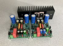
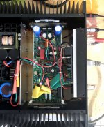
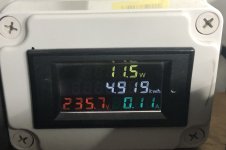
Just to let you know that the Q17-Mini's production PCB 1.1.1 works without a hitch. I built one and installed it in the cabinet.
One board consume 11.5W.
On the other hand, I have to order components for the second card again. With all my tests and burnt components, I am missing some now.
Cheers,
Stef.
Attachments
Last edited:
No, I would like to keep the prototype to tinker with and assemble a board with the final PCB to put in the cabinet.
I'm still going to tinker to use both cards at the same time to test in stereo.
Tibi, could you look on Mouser to find me a suitable Schottky diode? I am a little lost with all these references, the Fv which are given for different consumption and the out of stock problem.
Stef.
I'm still going to tinker to use both cards at the same time to test in stereo.
Tibi, could you look on Mouser to find me a suitable Schottky diode? I am a little lost with all these references, the Fv which are given for different consumption and the out of stock problem.
Stef.
https://uk.farnell.com/multicomp-pro/1n5819/schottky-diode-1a-40v-do-41-full/dp/1843512?st=schottky
@ low current, Vf should be around 300mV
Regards,
Tibi
@ low current, Vf should be around 300mV
Regards,
Tibi
Tim,Hello,
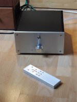
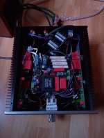
I have built another Q17, this time a copy of the flatter one, but with soft start, speaker delay and speaker protection circuit, and radio controlled potentiometer.
Plays great.
Regards Tim
You have an original way to put things together. 😀👍
How do you like and compare the amplifier sound ?
Regards,
Tibi
https://uk.farnell.com/multicomp-pro/1n5819/schottky-diode-1a-40v-do-41-full/dp/1843512?st=schottky
@ low current, Vf should be around 300mV
Regards,
Tibi
Sorry Tibi but there must be something I didn't understand.
The 1N5819 is given for a Fv of 450mV far away from 350mV.
Stef.
And this 1N5819 from ST?
https://www.mouser.fr/datasheet/2/389/cd00001625-1795544.pdf
Or the SB series from Vishay?
https://www.mouser.fr/datasheet/2/427/VISH_S_A0003154141_1-2568705.pdf
Attachments
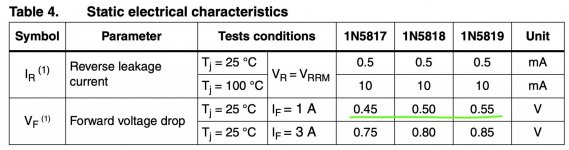
Vf is a function of If - forward current. At 1A Schottky diode will have a forward voltage of 0,55V, but under 100mA this will be around 300mV.
Look for datasheet graphs.
In our case If is under 5mA.
Regards,
Tibi
Look for datasheet graphs.
In our case If is under 5mA.
Regards,
Tibi
Last edited by a moderator:
Hello Tibi,
I built the amp because the first one
https://www.diyaudio.com/community/...approach-to-perfect-sound.374507/post-6776372
has already moved out to an excessive speaker hobbyist and I want to have that as a comparison, also to test the additional comfort functions. It is nearly the same, but with a 120VA 2x 24V Transformer (even less Current).
Currently I am building an amplifier based on the latest PCB creation of mine, which contains additional components and of course I want to know if these modifications somehow make themselves noticeable.
Regards Tim
Vf is a function of If - forward current. At 1A Schottky diode will have a forward voltage of 0,55V, but under 100mA this will be around 300mV.
Look for datasheet graphs.
In our case If is under 5mA.
Regards,
Tibi
Thank you. This time it's good. Understood. 😉
Stephane
Hello,
I can now make a comparison:
the one amplifier corresponds to this setup:
https://www.diyaudio.com/community/...approach-to-perfect-sound.374507/post-6776342This one plays especially airy, exceptionally natural.
With the new amplifier I have integrated more components to test their effects:
1. a subber link at Q12, this reduces the resolution, the stage becomes narrower.
I removed the subber at Q12 first, it disturbs.
2. resistors against ground at the signal paths to the end transistors, this has no audible effect (after the simulation should also only show an effect with some more end transistors).
The resistors against ground are also removed. They showed no effect in this variant.
3. R11 and R12 are 51 Ohm
This is also a stupid idea, contrary to the simulation the amp becomes more unstable, the DC offset increases to 56 mV. After it warmed up a bit it didn't find a DC operating point, only after reducing it to 47 ohms it works as usual.
4. R3 is 100 Ohm
I cannot say anything about this yet.
5. C-Q5 and C-Q6 is 470pF
This has a subtle effect, it takes away some airiness and leads to a more precise structuring of the acoustic stage, the amp tends to play more analytically.
6. the PCB is very much downsized and there are 2200 uF installed (cup electrolytic capacitor), on the other only 820 uF (low ESR). The cup electrolytic capacitor does not seem ideal, the bass is more controlled and therefore a bit more restrained.
My conclusion: Q17 tuning is nearly impossible - so I say: Tibi you did an excellent job.
Regards Tim
Tim,Thank you very much for your feedback, Tim !
Regards,
Tibi
Thanks for the feedback, I'm still waiting for the feedback on the three pair output amps. Did anyone build a three pair output amp yet ?
- Home
- Amplifiers
- Solid State
- Q17 - an audiophile approach to perfect sound