KSC2690A KSA1220A are pretty good drivers and available.
@peufeu, I agree with your comments on CFP.
Here are more issue regarding CFP that I found.
1. It is hard to let CFP 100% stable. It's prone to ring even it is stable. Any attempt to compensate/degenerate CFP will kill it's speed/bandwidth. Leave you less phase margin you could work with on the entire amplifier.
2. CFP is a fast-on / slow-off device by nature. Its turn-off speed is much slower than its turn-on speed. It can short the +/- power rail when it goes into high frequency oscillation.
Basically: In all modern power amplifiers, the output stage is current-driven, ie driven from a relatively high impedance
This may not true. With Miller cap, vas may behave like voltage source instead of current source at high frequency.
We wish all the ops should be current driven, so that the imperfections of ops gm will not be reflected at the output.
Alright!
Thanks Bimo 🙂
ojg>
I've tried several base resistor values for the MJL1302/3281 and got it down to 1.8 ohms and it isn't oscillating yet. Now that I think about it, with zero ohms it did get unstable, but only when excited by HF from the network analyzer. Right now I'm not seeing any suspicious HF misbehavior on the scope when testing with audio frequencies.
I've lowered driver base resistance to 15R, current gain measurement is a bit noisy but still readable.
> 20R base resistor on the BJT output transistors is too high. It will modulate the idle current of the output stage with the signal.
Yes, theory says it will make it behave like it has less bias, so it's a waste of bias.
> It will also make the output stage more dependent on beta matching between P and N transistors. Cordell mentions this in his book.
...which means the next thing I should try is to put a slightly higher base resistor on the MJL that has more hFe, so they get the same voltage drop under the same output current. That won't solve the driver hFe mismatch though. I could also play with the driver base resistors, but that won't model the interaction of varying hFe with the VAS output impedance. Still... it's a cheap mod, so I will do a before/after test.
No time now, I will try that later today, so meanwhile, if you have other ideas, go ahead!
This may not true. With Miller cap, vas may behave like voltage source instead of current source at high frequency.
I was implying 2 pole compensation, but yeah, I think I've overestimated the VAS output Z, if the VAS is proper (ie, at least a darlington, for lots of gain).
We wish all the ops should be current driven, so that the imperfections of ops gm will not be reflected at the output.
But then you get hFe mismatch instead (except with FETs).
Yeah I have the book. Only problem with that is the MOSFET models he used are correct for latfets, but not for verticals, which give a much smoother gm vs current...
Hi peufeu,
Just set the diamond buffer up as you normally would. I normally see around 50 mA output bias in practice (in the ballpark). But no harm in making the output bias the same as your other output arrangements to compare apples to apples.
No rush, it is work and I thank you for your efforts. We are learning a lot. I don't see it as a contest between output types and configurations. Everything has pros and cons. Knowing the characteristics will allow us to make the best choices for us for each output configuration. There is the true value in what you are doing.
Too many people want to use "the best", but that depends an many variables. Depends on your goals, performance requirements and probably budget. Life isn't that easy.
-Chris
Hmmmmmmm
With 1R8 base resistors, I don't see anything wrong on the scope, but all the distortion plots look like they're high on magic mushrooms. I'm gonna increase it a bit...
OK let's make sure there are no misunderstandings...

If that's what you mean, then these will need Io = max(Iout)/hFe so if the devices have hFe of 100 to get 5 amps output that needs 50mA CCS, which I think would be better spent in increasing the bias... Unless you meant diamond predrivers, which need a lot less idle current.
Thanks for the kind comments! Yes, I agree about the art of compromise...
With 1R8 base resistors, I don't see anything wrong on the scope, but all the distortion plots look like they're high on magic mushrooms. I'm gonna increase it a bit...
Hi peufeu,
Just set the diamond buffer up as you normally would. I normally see around 50 mA output bias in practice (in the ballpark). But no harm in making the output bias the same as your other output arrangements to compare apples to apples.
OK let's make sure there are no misunderstandings...
If that's what you mean, then these will need Io = max(Iout)/hFe so if the devices have hFe of 100 to get 5 amps output that needs 50mA CCS, which I think would be better spent in increasing the bias... Unless you meant diamond predrivers, which need a lot less idle current.
Thanks for the kind comments! Yes, I agree about the art of compromise...
My secret sauce for base stop resistor.
Power Transistor: 10 Ohm
Driver (TO-126 Package): 68 Ohm
Pre-Driver (TO-92 Package): 100 Ohm
Power Transistor: 10 Ohm
Driver (TO-126 Package): 68 Ohm
Pre-Driver (TO-92 Package): 100 Ohm
Hi peufeu,
Yes, that is what I meant. Thank you.
However, I am unfamiliar with the diamond buffer type drivers, so can you show me or is it too complicated a circuit to test? I don't want to create a ton of work for you unless there is actual merit in doing something.
Emitters are 0R15 like everything else? (Good!)
-Chris
I just did a sim with the Pass New Stasis output stage with MJL1302A & MJL3281A, manually set at Iq = 0.1A & Vos < 1V:
- Rb = 22R: THD: 0.831556%
- Rb = 2.2R: THD: 0.692364%
However, I am unfamiliar with the diamond buffer type drivers, so can you show me or is it too complicated a circuit to test? I don't want to create a ton of work for you unless there is actual merit in doing something.
It's not a complicated circuit, but what bothers me is the fact the drivers are burning a lot of current idling. Since they're upside down, they can only substract current from what the current source provides to feed base current to the power devices, so the current source needs to be sized for "maximum base current of all time"...
>Emitters are 0R15 like everything else? (Good!)
0R33 for the bipolars, keeps the bias more stable.
I've got distortion that shouldn't be there, it's odd harmonics only (no even), it depends on the level of the 12kHz tone but does not depend on the output current of the DUT at all (it is also present in the output with no load).
So it is probably in the input signal.
It just appeared, and the "interesting" thing is... sometimes it goes away. And then it comes back, without changing anything...
Pretty annoying, because I finally got the setup and the software to do what I want, and it decides to throw a tantrum.
Obviously the first thing that comes to mind about "stuff that works intermittently" is software, so I hope it's not the soundcard drivers...
Hi peufeu,
Argh! Sorry to hear about your test setup. Have you looked at the waveform with a 'scope yet? Hopefully it will resolve easily.
-Chris
Yes, you're right. That's why the outputs are normally done as a darlington pair before the upside-down drivers. This reduces the standing current in the current sources to reasonable levels. I've only seen the circuit as you showed in signal applications (at lower current levels and lower voltages).... what bothers me is the fact the drivers are burning a lot of current idling. Since they're upside down, they can only substract current from what the current source provides to feed base current to the power devices, so the current source needs to be sized for "maximum base current of all time"...
Argh! Sorry to hear about your test setup. Have you looked at the waveform with a 'scope yet? Hopefully it will resolve easily.
-Chris
This THD vs level plot sure looks dodgy lol
It's on the input

Found the culprit 😀 wiggling the output connector on the soundcard solved it...

It's on the input
Found the culprit 😀 wiggling the output connector on the soundcard solved it...
Last edited:
Alright, we're back in business.
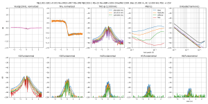
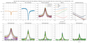
Here is what is being tested:

Since we had a debate about the VAS output impedance... Well I can't tell how big yours is, but I can put in different resistor values in the place labeled "Z" on the left of the schematic, which is in series with the TPA6120 composite amp driving this thing, and that will tell us what happens when the VAS (or predriver) output impedance varies between 10R, 150R, 1k. The value is in the title of the plots before the word "Bias".
In this test the DUT is driven from the input with 12kHz sine of varying amplitude.
- Load is 8R
- The large DC operating point current of the output stage (from -2.5A to +2.5A) is on the X axis of all the graphs except the top right two
- Upper left plot is the output amplitude at 12kHz, that varies because the output impedance of the DUT (=1/gm) forms a divider with the 8R load, so it is basically gm plotted in dB. It is normalized to 0dB to make it easy to compare between different circuits while switching between pictures. No surprises: since current gain depends on polarity of output current, increasing the driving impedance tilts the high current sides of this plot up and down.
- "hFe" plot is the current gain of the output stage, again normalized and in dB for easier comparison.
- "THD" is the sum of the harmonic plots below which each represent one harmonic of the 12kHz signal ; all distortion plots are in dB relative to fundamental
- "Metrics" is various ways of turning this THD into an easily digestible number. X axis is the amplitude of 12kHz current, and the plots are the max and min THD at all output currents, the THD close to zero output current which would be the "official" measurement, and a "GedLike" weighted average.
- "Unloaded harmonics" is the harmoncis (in color) and THD (in black) of the 12kHz tone through the output stage without 8R load on the output.
Results:
150R driving impedance gives a slight increase in distortion vs 0R
1k driving impedance gives a substantial increase in distortion at high output current, therefore far from the crossover region: this is most likely due to nonlinear input capacitance and Early effect. But in the crossover, the hFe variation between both devices only increases distortion a bit. At 150R gm dominates distortion, and I'd say at 1k both gm and hFe variations contribute equally.
Here is what is being tested:
Since we had a debate about the VAS output impedance... Well I can't tell how big yours is, but I can put in different resistor values in the place labeled "Z" on the left of the schematic, which is in series with the TPA6120 composite amp driving this thing, and that will tell us what happens when the VAS (or predriver) output impedance varies between 10R, 150R, 1k. The value is in the title of the plots before the word "Bias".
In this test the DUT is driven from the input with 12kHz sine of varying amplitude.
- Load is 8R
- The large DC operating point current of the output stage (from -2.5A to +2.5A) is on the X axis of all the graphs except the top right two
- Upper left plot is the output amplitude at 12kHz, that varies because the output impedance of the DUT (=1/gm) forms a divider with the 8R load, so it is basically gm plotted in dB. It is normalized to 0dB to make it easy to compare between different circuits while switching between pictures. No surprises: since current gain depends on polarity of output current, increasing the driving impedance tilts the high current sides of this plot up and down.
- "hFe" plot is the current gain of the output stage, again normalized and in dB for easier comparison.
- "THD" is the sum of the harmonic plots below which each represent one harmonic of the 12kHz signal ; all distortion plots are in dB relative to fundamental
- "Metrics" is various ways of turning this THD into an easily digestible number. X axis is the amplitude of 12kHz current, and the plots are the max and min THD at all output currents, the THD close to zero output current which would be the "official" measurement, and a "GedLike" weighted average.
- "Unloaded harmonics" is the harmoncis (in color) and THD (in black) of the 12kHz tone through the output stage without 8R load on the output.
Results:
150R driving impedance gives a slight increase in distortion vs 0R
1k driving impedance gives a substantial increase in distortion at high output current, therefore far from the crossover region: this is most likely due to nonlinear input capacitance and Early effect. But in the crossover, the hFe variation between both devices only increases distortion a bit. At 150R gm dominates distortion, and I'd say at 1k both gm and hFe variations contribute equally.
Attachments
-
 thd-MJL1302-3281 v5 EF2 Re=0R33+4R7 Rb=3R8 MJE1503-1 Rb=15 Re=68R+100n DriveMid-B=25.0m,HA=4.0m,.png261.8 KB · Views: 402
 -
 thd-MJL1302-3281 v5 EF2 Re=0R33+4R7 Rb=3R8 MJE1503-1 Rb=15 Re=68R+100n DriveMid 150R-B=25.0m,HA=.png263.8 KB · Views: 372
 -
 thd-MJL1302-3281 v5 EF2 Re=0R33+4R7 Rb=3R8 MJE1503-1 Rb=15 Re=68R+100n DriveMid 1k-B=25.0m,HA=4..png308.5 KB · Views: 395
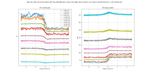
Does the 100nF cap between the driver emitters help with the hFe mismatch?
Answer: no, it is there only to help turn-off. No difference in the input current with and without the cap.
Note hFe mismatch of both halves of this output stage depends on frequency. At high frequency they match, at low frequency they have quite large mismatch. I'm not sure of the cause, but well, at low frequency the mismatch is only due to hFe, and at higher frequency the various capacitances and transition frequencies come into play, and there is no reason for both hFe and capacitance to have the same matching (or mismatch).
So, feedback increases at low frequency, but this error also increases accordingly, which means it's a draw.
Also this frequency dependent behavior adds difficulty to trying to correct it...
Attachments
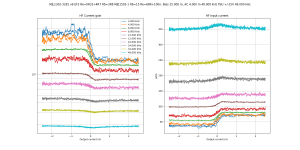
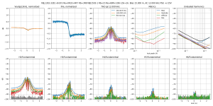
Alright. After comparing the influence of VAS output impedance on the EF2, I'll also do it on the "DarlingEF".
Since the pure Darlington sucked too much at turning the transistors off in the dynamic test, I made a "DarlingEF" by starting with the EF2 in the previous post, and adding two 47R resistors across the B-E of the power devices. I left the 100nF cap and the 68R resistor in. This gives the same gm and current gain as the darlington, but the drivers don't turn off and it has better dynamic behavior.
Due to the resistors across the B-E of the power devices, some of the driver bias current now counts as total bias, and there is a temptation to just leave the drivers on at idle, turning off the main transistors.
This is a bad idea.
Since it's real cheap to save a couple milliamps, I also tested with a cheap 1K VAS output impedance, versus EF2 at the same bias and same conditions.
It is not even necessary to enlarge the thumbnails to see which one has highest distortion...
Attachments
Yes, any departure from the input signal is work for the error amp (diff pair in most cases). That's why your work is so important. The more linear current gain stage will reduce overall distortion.
Hang a scope probe at the beginning of the current amp stage to see what nasties are being corrected. That waveform will be approximately inverted compared to the actual non-linearity of the output stage. This is something for everyone, it isn't what I am asking you to do peufeu. The work you are doing is quite enough!
-Chris
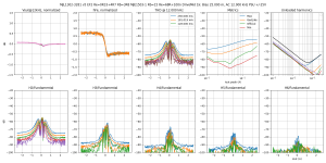
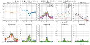
One interesting feature of the Darlington (and DarlingEF) is that its current gain is flatter than that of the EF2.
So, I stepped the bias until the high order harmonics no longer went further down, which gives close to optimal bias, in this case 30mA, and I compared it to EF2, again with 1k VAS impedance...
In addition, both have 18mA driver bias due to the 68R resistor between driver emitters. The plot titles only mention bias current through the power emitter resistors, which is what the ADC measures.
Result:
At 30mA bias, DarlingEF gives more distortion than EF2.
At 15mA bias, DarlingEF collapses (previous post) but EF2's performance is not significantly worse than at 30mA.
Conclusion: EF2 gives the same performance at half the bias, which is a win.
I think this is due to the fact the drivers are less loaded in the EF2, so they distort less (ie, gm is flatter).
Attachments
-
 thd-F=12k-MJL1302-3281 v6 DarlingEF2 Re=0R33+4R7 Rb=3R8 Rbe=47 MJE1503-1 Rb=15 Re=68R+100n Zin=1.png287.5 KB · Views: 150
 -
 thd-F=12k-MJL1302-3281 v6 EF2 Re=0R33+4R7 Rb=3R8 MJE1503-1 Rb=15 Re=68R+100n Zin=1kB=30.0m,HA=4..png279.6 KB · Views: 108
 -
 thd-F=12k-MJL1302-3281 v6 EF2 Re=0R33+4R7 Rb=3R8 MJE1503-1 Rb=15 Re=68R+100n Zin=1kB=15.0m,HA=4..png281.1 KB · Views: 109
- Home
- Amplifiers
- Solid State
- Power amp OUTPUT STAGE measurements shootout