Bootstrapped cascode removes >90% of Cgd and >90% of Cgs. But it forces you to spend additional money on additional VAs for your power transformer. Same I, bigger V, thus bigger I*V product. More money for higher voltage rail caps too. Oh and twice as many output transistors ... but less dissipation per device so greater reliability.
Fortunately I had exactly four "amazon basics, for the discriminating sucker" 9V batteries available.

It does the expected thing to input capacitance:

X axis is the output voltage, so when the cascodes have enough Vgs, they work. When they're squeezed against the rails, they don't work, and it's like not having them, with a slight loss of headroom due to RdsON.
I did not use higher voltage bench power supplies (due to not having any) but this shows you don't have to increase VCC to use cascodes, of course they won't work on all the output voltage range, but unless the amp is really underpowered, going over half the max output voltage only occurs on peaks, where the loudspeakers and ears distort hugely anyway, so the cascodes should work 99% of the time.
(the dependence on frequency seems to be an effect of the test setup, as it also manifested when using it to measure the capacitance of a 10nF cap).
BUT does it do anything to distortion?
The answer seems to be a solid "meh" ; in other words, the extra idle watts and complexity are better invested in brute force, ie, more bias current.
Attachments
Basically, at low output voltage, Cgd is pretty constant, so it doesn't contribute much to distortion, and especially to high order harmonics.
So the cascode makes Cgd appear lower, which does require less drive current. But, since it is not a very nonlinear capacitance until the amp is close to clipping anyway, is there a point in making it lower?
On the plus side, it does spread the dissipation between two devices in a different way than paralleling.
If the previous test (paralleling while sharing the same total bias) had failed, then I would have been ready to use one FET at high bias with a cascode to handle the dissipation. But the test worked...
Last edited:
I don't understand everything, but I find it very interesting! I hope you can make a summary for dummies later 🙂 Keep up the good work!
+1
//
Lately, I like to used Triple Emitter Follower with pre-driver bootstrap. It is cheap, but PSRR increase, THD and slew rare decrease. Can you analyze it?
Lately, I like to used Triple Emitter Follower with pre-driver bootstrap. It is cheap, but PSRR increase, THD and slew rare decrease. Can you analyze it?
That could be interesting...
Right now I did a comparison between IRFP9/240 while changing gate resistors: 150R vs 1500R. There is an extra 20R resistor in series on the board, so it's actually 170 vs 1520 but well.
Results with higher resistor value:
- Input capacitance, current gain: no change
- Loss of apparent gm with output near the rails: the higher gate resistor enhances the effects of the increased input capacitance of the MOSFET that is squeezed against the rail. On the plots, this shows up as the gm curves that should have been in the empty circles moving down to where the arrows point. This loss of gm where it is needed (high current, low headroom) is undesirable.

- Increase of all distortion harmonics: below plots are comparison of 150R vs 1520R driving impedance.
Comparison between 71R and 170R: no difference.
Conclusion: if FETs are voltage driven, keep gate resistor low and driving impedance low.
Attachments

Last edited:
350R source resistance is also worse than 150R, so I guess "source resistance below 150R" would be a good starting point, and it doesn't hurt to make it lower.
Hi peufeu,
Yes, Nelson knows exactly what he is doing. He plays with the devices on a bench and tests everything with an open mind. I have a lot of respect for that.
However, I don't like things that run hot, so at lower temperatures it seems the BJTs have a lot going for them. Of course, your experiments so far have been extremely informative.
Yes. Still reading with great interest!
Independently of local considerations, increased gate resistors move parasitic poles lower in frequency, hurting the GNFB margins.Right now I did a comparison between IRFP9/240 while changing gate resistors: 150R vs 1500R. There is an extra 20R resistor in series on the board, so it's actually 170 vs 1520 but well.
Results with higher resistor value:
- Input capacitance, current gain: no change
- Loss of apparent gm with output near the rails: the higher gate resistor enhances the effects of the increased input capacitance of the MOSFET that is squeezed against the rail. On the plots, this shows up as the gm curves that should have been in the empty circles moving down to where the arrows point. This loss of gm where it is needed (high current, low headroom) is undesirable.
View attachment 968179
- Increase of all distortion harmonics: below plots are comparison of 150R vs 1520R driving impedance.
Comparison between 71R and 170R: no difference.
Conclusion: if FETs are voltage driven, keep gate resistor low and driving impedance low.
Basically, if the layout is good enough, making the stoppers=0 is the best solution.
The second best is to use ferrite beads: they suppress VHF instabilities with a minimal effect on the rest

However, I don't like things that run hot, so at lower temperatures it seems the BJTs have a lot going for them. Of course, your experiments so far have been extremely informative.
Thanks! I'll run the same stuff on the BJTs but that requires setting all the gains for base current etc. So, I will finish with the FETs first.
Speaking of which, time for the network analyzer to come out.

The rest of the setup adjusts the DC voltage at the input to keep the output at 0V DC, then the Modulus 86 sends a DC voltage through the 8R resistors to set output current. Since the output impedance of the Modulus isn't specified at RF, the capacitor in the middle ensures that the DUT will see something that is reasonably close to 8R starting from about 50kHz.
I put a 1R SMD resistor in parallel.

So the VNA injects a signal at the input, and measures the output. I think something weird happened to the phase, I'll investigate later.
But wtf is happening at 10MHz?

Oh my

Looking at the curves (I put labels on them) it appears that the ugliness only manifests when the DC output current is high enough to turn off one MOSFET. When both MOSFETs are on, at low output current, it's clean.
This points to the MOSFET being off acting as a capacitive load for the other MOSFET. But where is the inductor? I remember buying these "non-inductive" resistors... but it turns out there is no mention of "non-inductive" anywhere, I must have misremembered it.
The VNA measures a ridiculously huge inductance on these, somewhere around 200nH.
So I put a 1R SMD resistor in parallel with the 0R15 "inductor with resistive properties"
This combo has a 1R//0R15 = 0R13 resistance at DC, then its impedance goes up with the 200nH inductance of the wirewound resistor, then it shelves at 1R above 1MHz. I feel this is better than a non-inductive 0R15 resistor, because it provides more damping at high frequency against stray inductance.
After adding the 1R SMD resistors, ringing is completely eliminated and the output is very clean.
Attachments
I think I've found totally by chance the reason why some people report important differences in sound between various sorts of emitter resistors.
TL/DR:
The mechanism: when one transistor is off, it becomes just a capacitor, that forms a LC with the inductance of its emitter/source resistor and it rings. This does not manifest when both transistors are on.
The fix: add damping, 1 or 2 ohms very low inductance SMD resistor in parallel with the big inductive one. I've used 2220 1W thick film.
It is also possible to DIY some cheap low inductance resistors, by making a small piece of PCB with SMD resistors on it. If it is mounted vertically it would act as a heat sink too.
Yes, inductive emitter resistors cause all kinds of problems that I have solved by using the "plate" resistors. Of course you solution works wonders too.
-Chris
-Chris
Excellent!
It is now doing a ton of VNA sweeps while stepping power supply voltages to check what happens when it gets near the rail...
It is now doing a ton of VNA sweeps while stepping power supply voltages to check what happens when it gets near the rail...
I swear peufeu, you're beginning to have some real fun! 🙂
You are doing some excellent work, thank you.
-Chris
You are doing some excellent work, thank you.
-Chris
It's a really interesting project 😀
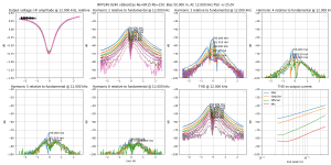
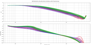
Output current is stepped -2A .. 2A ; FET supply voltage from 2V to 25V (for both).
There are way too many plots on this plot, so I used a color gradient, it's basically RGB.
Both FETs have a lot of headroom: green.
Bottom FET getting squeezed by low headroom: blue
Top FET getting squeezed by low headroom: red
Any FET with less than 5V headroom: dashed line (these ones are pretty bad).
Attachments
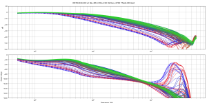
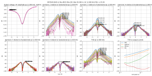
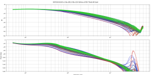
I have removed all curves with less than 5V headroom, it seems worthwhile to sacrifice a bit of headroom here.
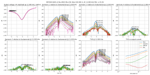
This shows these devices can do ULGF of 10MHz, keeping a safety margin from the mess happening around 20-30MHz. That sounds good.
This is with a Thiele network in the output. It is running another sweep without it.
This shows these devices can do ULGF of 10MHz, keeping a safety margin from the mess happening around 20-30MHz. That sounds good.
This is with a Thiele network in the output. It is running another sweep without it.
Attachments
Independently of local considerations, increased gate resistors move parasitic poles lower in frequency, hurting the GNFB margins.
Basically, if the layout is good enough, making the stoppers=0 is the best solution.
The second best is to use ferrite beads: they suppress VHF instabilities with a minimal effect on the rest
Yes ��
I like my hacked emitter resistors: 0R15 at audio frequency, 1 ohm resistive at 1MHz. I will try to increase the value of the SMD resistor I put in parallel with the big inductive ones. Perhaps if I manage to squeeze in a few extra ohms it will add enough damping to the circuit to lower the gate resistors more without getting instability. Maybe it would even allow to get rid of the zobel.
I don't know if this will work, it's just a hunch.
The 1µF MLCC decoupling caps on the board also have 1R resistors in series for damping.
Having low gate resistor values has another advantage: it makes the capacitance difference between the two FETs less problematic when one has low headroom thus higher capacitance. With high value gate resistors, when trying to un-stick the top FET from the rail, the drivers will pull current from both gates. The bottom FET has much lower capacitance at its high Vds, so if everything goes perfectly wrong it will turn on before the top FET un-sticks from the rail, and this causes cross conduction when coming out of clipping. If the amp oscillates this can cause smoke...
However I'm not going to tweak the gate resistor values now because that's a job to do on a finished amp layout... Too many jumpers, resistors on headers, and wires on this one.
Last edited:
I was wondering "hey, there's this thing with the small fast class A stage in parallel with the big slow class B stage, so..."
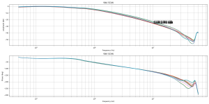
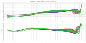
If summing at the output is involved, I will also measure the output impedance.
Color coding is the same as previously. Zout is pretty civilized, and the hacked emitter resistors make Zout higher at HF, which would be useful, in case I decide to use this plan... I have some ideas about that.
If summing at the output is involved, I will also measure the output impedance.
Color coding is the same as previously. Zout is pretty civilized, and the hacked emitter resistors make Zout higher at HF, which would be useful, in case I decide to use this plan... I have some ideas about that.
Attachments
- Home
- Amplifiers
- Solid State
- Power amp OUTPUT STAGE measurements shootout