Hang a scope probe at the beginning of the current amp stage to see what nasties are being corrected. That waveform will be approximately inverted compared to the actual non-linearity of the output stage.
Yes! Well that's basically what my instrumentation amps are doing.
Back to the EF2.
This time I wonder if a lower impedance between the driver emitters would help both drivers control each transistor better. So I put a diode in there and adjusted the resistor to get about the same driver bias.

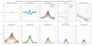
Compared to previous EF2 with 68R resistor instead of diode, this time at 6kHz which gives lower noise floor, 1k source impedance. The one with the diode is on the left.
There is basically no difference.
Attachments
The same, without the 1k driving impedance...
Again, no difference.
Again, no difference.
Attachments

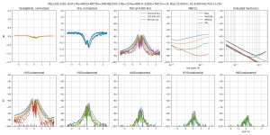
Went back to the EF2 configuration, but moved the 68R resistor from between the drivers' emitters to the power transistor bases. Thus variation of base current in the power devices cause a bit of variation in the driver bias.
Result: distortion increases slightly near zero.
Result: distortion increases slightly near zero.
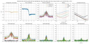
Since the pure Darlington sucked too much at turning the transistors off in the dynamic test, I made a "DarlingEF" by starting with the EF2 in the previous post, and adding two 47R resistors across the B-E of the power devices. I left the 100nF cap and the 68R resistor in.
I use this to speed up "turn off" in my project. It really helps to match the current gain of npn and pnp at high frequency. At least, they don't fight each other due to the slowness of turning off.

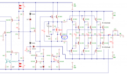
PS: The snapshot shows the last 2 stages (driver and power stages) of a 3EF output stage.
Last edited:
Actually, the comparison between difference of vas impedance may give you wrong impression.
"The lower the impedance is, the lower the distortion"
-- which may be wrong, when global feedback is applied.
If keep the same open loop DC gain, the lower the impedance of vas, that means more local feedback around vas and miller cap. That also suggest less global nfb, which leads to more uncorrected distortion. It is the same mechanism that THD rises when frequency gets high.
Do the diodes conduct at idle or just to help turn off one of the transistors?
The diodes is conducted.
Acturally, they have to be conducted (at least partially) to let power transistor get meaningful bias.
If keep the same open loop DC gain, the lower the impedance of vas, that means more local feedback around vas and miller cap. That also suggest less global nfb, which leads to more uncorrected distortion. It is the same mechanism that THD rises when frequency gets high.
Yes I thought TMC compensation, which increases useful feedback around the output stage, would also increase VAS output impedance, but... in fact I'm not so sure about it. I have to do some spicing.
YI wonder if a lower impedance between the driver emitters would help both drivers control each transistor better. So I put a diode in there and adjusted the resistor to get about the same driver bias.
What a lovely idea! Bravo, congratulations.
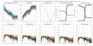
To get a better hFe match, we need a circuit that looks at the emitter current of one transistor and injects a current in the input that compensates for the difference in base current due to hFe mismatch. Since the emitter resistor provides a voltage that mirrors the emitter current in one transistor, the simplest circuit to do the deed is...

One resistor. Its value depends on hFe, so it has to he adjusted. In this case it is about 7.8 kOhms.
The left side of this resistor doesn't have to be on the right side of the driver base resistor, it should actually be on the other side, but I put it there because the instrumentation amps measure the current on the driver base resistors...
The resulting current gain is flat, save for a dimple in the middle because some Vbe is also included in the compensation voltage across the resistor. Compare with the version without the resistor in this post.
And the fact it's a high value resistor that only lets through a tiny amount of current means it doesn't do anything at high frequency, so the compensation works across the whole range. No more step in the current gain!

But does it do anything? Now that's another question! With the driving impedance set to "zero" (actually 10 ohms protection resistor on the opamp)... it doesn't change anything at all.
I launched another run with 1k source impedance.
One resistor. Its value depends on hFe, so it has to he adjusted. In this case it is about 7.8 kOhms.
The left side of this resistor doesn't have to be on the right side of the driver base resistor, it should actually be on the other side, but I put it there because the instrumentation amps measure the current on the driver base resistors...
The resulting current gain is flat, save for a dimple in the middle because some Vbe is also included in the compensation voltage across the resistor. Compare with the version without the resistor in this post.
And the fact it's a high value resistor that only lets through a tiny amount of current means it doesn't do anything at high frequency, so the compensation works across the whole range. No more step in the current gain!
But does it do anything? Now that's another question! With the driving impedance set to "zero" (actually 10 ohms protection resistor on the opamp)... it doesn't change anything at all.
I launched another run with 1k source impedance.
Attachments
Last edited:
Sooooo... with 1k source impedance, does the flatter current gain help?
At 25mA bias, it does reduce H2 a little bit, by about 5dB. But it is not spectacular.
Two values of bias are shown, two on the right don't have hFe mismatch compensation resistor, two on the left do.
At 25mA bias, it does reduce H2 a little bit, by about 5dB. But it is not spectacular.
Two values of bias are shown, two on the right don't have hFe mismatch compensation resistor, two on the left do.
Attachments
-
 thd-F=6k-MJL1302-3281 v6 EF2 Re=0R33+4R7 Rb=3R8 MJE1503-1 Rb=15 Re=68R In-3281E=7k8 Zin=1kB=50.0.png277.3 KB · Views: 487
 -
 thd-F=6k-MJL1302-3281 v6 EF2 Re=0R33+4R7 Rb=3R8 MJE1503-1 Rb=15 Re=68R In-3281E=7k8 Zin=1kB=25.0.png274.2 KB · Views: 500
 -
 thd-F=12k-MJL1302-3281 v6 EF2 Re=0R33+4R7 Rb=3R8 MJE1503-1 Rb=15 Re=68R+100n Zin=1kB=25.0m,HA=4..png281.2 KB · Views: 443
 -
 thd-F=12k-MJL1302-3281 v6 EF2 Re=0R33+4R7 Rb=3R8 MJE1503-1 Rb=15 Re=68R+100n Zin=1kB=50.0m,HA=4..png289.2 KB · Views: 401
Last edited:
Amazing thread! 🙂
In the last diagrams it looks like the resistor decreases H2 but increases higher harmonics a bit? Seems there is a sharp glitch instead of the 'step' (hfe) and that would cause the higher harmonics if I'm not mistaken? I guess the feedback loop would also struggle more to correct the higher harmonics compared to H2?
In the last diagrams it looks like the resistor decreases H2 but increases higher harmonics a bit? Seems there is a sharp glitch instead of the 'step' (hfe) and that would cause the higher harmonics if I'm not mistaken? I guess the feedback loop would also struggle more to correct the higher harmonics compared to H2?
Last edited:
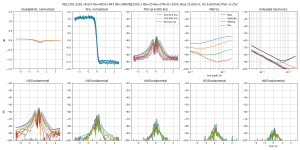
In the spirit of DIY, or "bring your own VAS output impedance", I realized after all this setup records base current. So why bother testing with several source resistor values when I can just apply ohm's law in software?
So here's the thing:
This is the distortion added to the output voltage only by variations in base current, with a simulated VAS output impedance of 1kOhm. Scale to your own value. This is basically input current*1kOhm which gives a voltage signal. Its harmonics can be computed, which means the distortion can be analyzed.
The basic EF2:

On top, "Delta Vout" is the distortion voltage that would be added to the output for a 1A peak output current, if the VAS output impedance was 1kOhm. Next is the current gain, and the input current of both drivers. Their hFe mismatch is apparent in the plot, they have completely different slopes.
On the bottom are distortion harmonics generated relative to fundamental output voltage. They are present only in the crossover zone, which is the center of the plot near zero output current. Level is low, but the sharp transition between one hFe and the other means they behave like a square wave: they almost don't fall off with increasing harmonic order. Pretty nasty.
This means if I used a lower test frequency to see higher harmonics, eventually the gm-related harmonics would fall off with increasing order, but these are quite persistent.
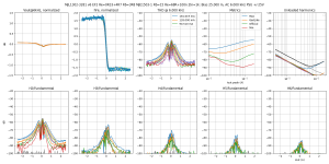
How does the circuit with the resistor in the previous post fare? Harmonics are down, but not that much. If I had not done this plot I would have never known...

So here's the thing:
This is the distortion added to the output voltage only by variations in base current, with a simulated VAS output impedance of 1kOhm. Scale to your own value. This is basically input current*1kOhm which gives a voltage signal. Its harmonics can be computed, which means the distortion can be analyzed.
The basic EF2:
On top, "Delta Vout" is the distortion voltage that would be added to the output for a 1A peak output current, if the VAS output impedance was 1kOhm. Next is the current gain, and the input current of both drivers. Their hFe mismatch is apparent in the plot, they have completely different slopes.
On the bottom are distortion harmonics generated relative to fundamental output voltage. They are present only in the crossover zone, which is the center of the plot near zero output current. Level is low, but the sharp transition between one hFe and the other means they behave like a square wave: they almost don't fall off with increasing harmonic order. Pretty nasty.
This means if I used a lower test frequency to see higher harmonics, eventually the gm-related harmonics would fall off with increasing order, but these are quite persistent.
How does the circuit with the resistor in the previous post fare? Harmonics are down, but not that much. If I had not done this plot I would have never known...
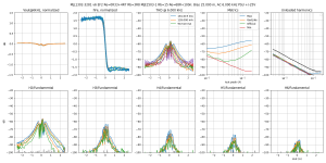
But what if we had transistors with adjustable hFe? This is possible, for example with a current mirror in the collector, or by using a CFP driver, current gain can be tuned with a few resistors. But to what value?
So I used scipy.minimize() on the distortion function to find out.
In this case it says distortion will be minimized if the top driver has its hFe increased by a factor of 2.86, or the bottom driver hFe should be divided by the same factor.
It then simulates what would happen if the hFe's were adjusted accordingly. So this plot is a simulation from measured data.
The autoscaling on the plots make it look like it's nothing special, but the current gain varies over a much smaller range.
The third plot on the top row is the THD as a function of the gain scaling applied on the driver that has too much hFe. The last two plots show top and bottom base currents before and after. The optimum does not correspond to what looks best, instead it equalizes the slope of the two base currents near zero output current.
All the harmonics are down at least 20dB, it is quite spectacular!
As the minimum of the distortion function has an inflection point with a round bottom, it means the value is not too critical to get right. It varies with frequency and bias, but not by much, it's always 2.7-2.8... which means it is implementable.
Since this costs one current mirror, I'm definitely going to try it tomorrow. I hope it works!
Attachments
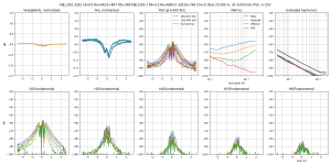
Here is an adjustable hFe transistor: its current gain is multiplied by the current mirror. Original is around 100, and the mirror gives the extra 1.8x, for a total of 280.
By removing the diode transistor and changing the resistor ratio, it becomes a CFP with much higher gain, which saves a predriver. The resistor ratio adjusts the current gain. If the bottom driver uses the same schematic, since all that matters is the ratio between the two, it's a matter of adjusting resistors to get a match.
By removing the diode transistor and changing the resistor ratio, it becomes a CFP with much higher gain, which saves a predriver. The resistor ratio adjusts the current gain. If the bottom driver uses the same schematic, since all that matters is the ratio between the two, it's a matter of adjusting resistors to get a match.
Attachments

Last edited:
But what if we had transistors with adjustable hFe?
Maybe you can just find a matched pair power transistor. 😀
Thanks for the resistor idea. In my amplifier, the output transistors MJL3281 & MJL1302 were with a spread of about 30% in hFe. I selected this resistor with a nominal value of 4k7 and thereby equalized the collector currents in each arm with an accuracy of tens of microamperes.
Attachments
Last edited:
Thanks for the resistor idea. In my amplifier, the output transistors MJL3281 & MJL1302 were with a spread of about 30% in hFe. I selected this resistor with a nominal value of 4k7 and thereby equalized the collector currents in each arm with an accuracy of tens of microamperes.
What kind of amp is it? Looks interesting..
- Home
- Amplifiers
- Solid State
- Power amp OUTPUT STAGE measurements shootout