AudioSan, I know. However, I'm pretty shure the colleague wasn't referring to the dissipation of the cooling aggregate which certainly is not 1000W.
Regards
Sven
Regards
Sven
thx for the intrest about the cooling. In practical terms we would use it to load power supplies during prototype testing. The 1000w would represent the needed load/ohm on a normal dc level . I have seen newer model of this cooling solution loaded with 400w without any issues. My particular one was used with loads of >300watts. i can also add that my colleague has some experience with amlifiers.
I've used this type of Chimney Heat Sink that was shorter than the one pictured with a slow/quite fan and dissapated a constant 500W without problems. I suppose 1000W would need a bit longer extrusion and a full speed fan 😉
Hi Pwrs.
Thanks for the cooling system info. This is the format I want to employ but was going to combine conventional sinks to form a tunnel as had been shown in a post about an F5T buildup. Are these types of sinks commercially available? If so, would you please provide a link or contact info?
Thanks!
Thanks for the cooling system info. This is the format I want to employ but was going to combine conventional sinks to form a tunnel as had been shown in a post about an F5T buildup. Are these types of sinks commercially available? If so, would you please provide a link or contact info?
Thanks!
hi pcb, and yes these are available within a couple of days. for lab testing elfa.se is fast where i live, or farnell,mouser,ms. i could probably get some more details on monday if you are looking fore specific order information.
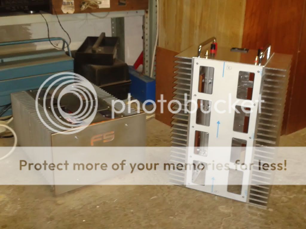
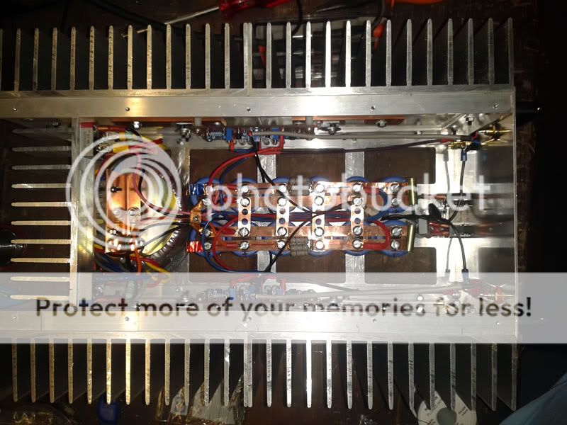
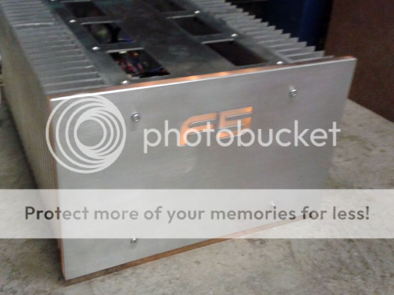
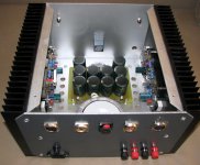
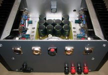
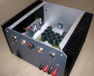
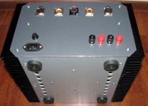
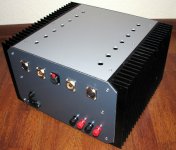
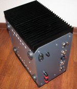
My F5 FirstWatt amp effort!!
Here she is, sem-completely. This has been a long and frustrating journey for me at times, solely, because of my own impatience sometimes...
But, I have finally gotten to the 99.5% completion stage..
with no cover..
with a custom logo perspex face plate:
with cover loosely fitted..
Thanx Mr Pass for a great sounding design!!
😀
Here she is, sem-completely. This has been a long and frustrating journey for me at times, solely, because of my own impatience sometimes...
But, I have finally gotten to the 99.5% completion stage..
with no cover..
An externally hosted image should be here but it was not working when we last tested it.
with a custom logo perspex face plate:
An externally hosted image should be here but it was not working when we last tested it.
with cover loosely fitted..
An externally hosted image should be here but it was not working when we last tested it.
Thanx Mr Pass for a great sounding design!!
😀
Congrats brother Prince, and I agree, we owe Papa Pass much!Thanx Mr Pass for a great sounding design!!
And since you started it... here's my first pair

Mind? MIND??Thats awesome Fdlsys. You mind if I copy😀
I'd be proud! No one copies the ugly stuff! 😀
I am in the glass industry, so this brings my hobby close to home. Had considered etched glass with just lettering clear, but it can be overpowqering. I really like you backlit version. did good job with proportions as well.
Shout of you need the recipe for the LED count and placing? BTW, I used 6mm acrylic sandwiched with 3mm Alu front. Nice balance if I may say so. Total weight was a concern, so everything was designed with that in mind....I really like you backlit version. did good job with proportions as well.
Amber light-show was intended at matching my valve pre-amp glow, and it does so perfectly! And the whole thing is a (subtle?) metaphor; F5 being as close as solid state can get to lush and rich valve-sound 😉
any chance you could attach more resolution than 160x91?
Here they are...
An externally hosted image should be here but it was not working when we last tested it.
An externally hosted image should be here but it was not working when we last tested it.
An externally hosted image should be here but it was not working when we last tested it.
😀
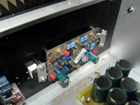
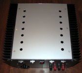
....my unfinished amplifier , missing some parts 😀
Alex.
Alex.
Attachments
-
 IMG_5432.JPG144.8 KB · Views: 1,921
 -
 IMG_5441.JPG130.8 KB · Views: 1,910
 -
 IMG_5443.JPG113.8 KB · Views: 1,023
 -
 IMG_5451.JPG109.6 KB · Views: 944
 -
 IMG_5452.JPG126.1 KB · Views: 822
 -
 IMG_5415.JPG104.2 KB · Views: 653
 -
 IMG_5409.JPG138.4 KB · Views: 506
 -
 IMG_5414.JPG139.2 KB · Views: 524
 -
 IMG_5416.JPG101.3 KB · Views: 485
Last edited:
terrible solution to the Thermal Dissipation!You are adding a lot of thermal resistance with the stacked cancer (aluminium oxide?) pads.
- Home
- Amplifiers
- Pass Labs
- Pictures of your diy Pass amplifier