
The inside of the chassis does heat up to about 50C after about 2 hours @nicoch58, but it seems to be stable after that so I don't know that I need to worry too much about it. If internal heat buildup does become a problem there is room for a small exhaust fan or two on the top cover. I have had it running for over 12 hours at a time while I was burning it in and the ambient temp was around 28C which is about as hot as my house ever gets. In the long run having the case run that hot is not going to be great for the electrolytics but I don't think I need to worry too much about that for 10 or 15 years. One thing that seems likely is that I will build myself a separate power supply box just for working with these First Watt amplifiers - I plan on building more of them for sure.
Also @Borats Baby those look very cool! Are those ACAs? Love the look.
Also @Borats Baby those look very cool! Are those ACAs? Love the look.
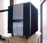
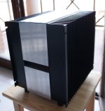
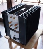
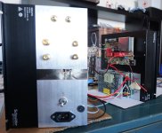
Last year built this little M2 from cheap materials. It's very simple and hand made. Two used (decommissioned) heat sinks from old inverters taken as they were (no mods), aluminium U shaped profile (10 cm x 2 cm x 2mm thick) for the central parts (those between the heat sinks), all the bolts are M3 except for the legs which are M6, pcb breadboard for prototypes cutting 2 corners for the mosfets, all the electronic made with point to point soldering using 0.8 mm nude copper wire, legs attached directly to the heat sinks using four M6 flanged nuts. Two Mean Well LRS-150-24 in series and surrounded by galvanized steel sheets (for RF isolation as precaution) are in the lower half of the enclosure (that remains open if view from the bottom). Top plate is not fixed and can be detached. Two blue leds inside.
The only "issue" (something that maybe could be improved) is that the Mean Well's LRS-150-24 gets hot as the enclosure gets hot (measured around 50 degrees Celsius). During initial tests (amplifier disassembled) both PS never got above 40 degrees. The enclosure is somehow little, measuring 21.5 cm width x 26.5 cm deep x 25 cm tall without legs. The upper part, where the boards are fixed is plenty of air once opened, but the lower part containing the PS, even if it's always open from below (no bottom part at all) do not have good air circulation in there. Hope the Mean Well's will endure the temperature stress. Until now they are fine.
The only "issue" (something that maybe could be improved) is that the Mean Well's LRS-150-24 gets hot as the enclosure gets hot (measured around 50 degrees Celsius). During initial tests (amplifier disassembled) both PS never got above 40 degrees. The enclosure is somehow little, measuring 21.5 cm width x 26.5 cm deep x 25 cm tall without legs. The upper part, where the boards are fixed is plenty of air once opened, but the lower part containing the PS, even if it's always open from below (no bottom part at all) do not have good air circulation in there. Hope the Mean Well's will endure the temperature stress. Until now they are fine.
Attachments
Last edited:

I don't know if I'm over thinking this now, but I've added small fans to the underside.
My heatsinks are sort of enclosed by wood. I don't know if that will hinder the heat dispersion or not...
Anyway, they are very quiet and any sort of cooling has to be a good thing? Yes?

My heatsinks are sort of enclosed by wood. I don't know if that will hinder the heat dispersion or not...
Anyway, they are very quiet and any sort of cooling has to be a good thing? Yes?
Keep in mind the air has to move through your enclosures to be effective. Add holes or create gaps so the fans can push or pull the hot air out.
Your amps look really nice, but ideally you’d have air moving along the fins of the heatsinks to take the heat away. I’m not familiar with the requirements of ACA heatsinking, so what you have may be enough.
Your amps look really nice, but ideally you’d have air moving along the fins of the heatsinks to take the heat away. I’m not familiar with the requirements of ACA heatsinking, so what you have may be enough.
Last edited:
Yes. Since I had to create a recess in the front and back panels (to make the hardware fit) there is now a gap at each end of the heatsinks.Keep in mind the air has to move through your enclosures to be effective. Add holes or create gaps so the fans can push or pull the hot air out.
Any air drawn in will be expelled through these gaps.
Purely accidental, but works in my favour.

- Home
- Amplifiers
- Pass Labs
- Pictures of your diy Pass amplifier