I most often listen on my electrostatic loudspeakers
Audiostatic ES300R (above 80Hz)
Should build a Pass ESL amp to drive them directly without step-up transformers. 😉
Semisouth JFET's: What are they good for?
Patrick
Last edited:
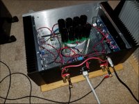
A few weeks ago I made a little stability test (check pics) for your fun....
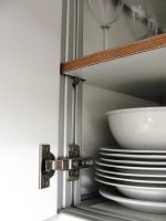
Let me show you something else from those extrusions.
Patrick
.
Attachments
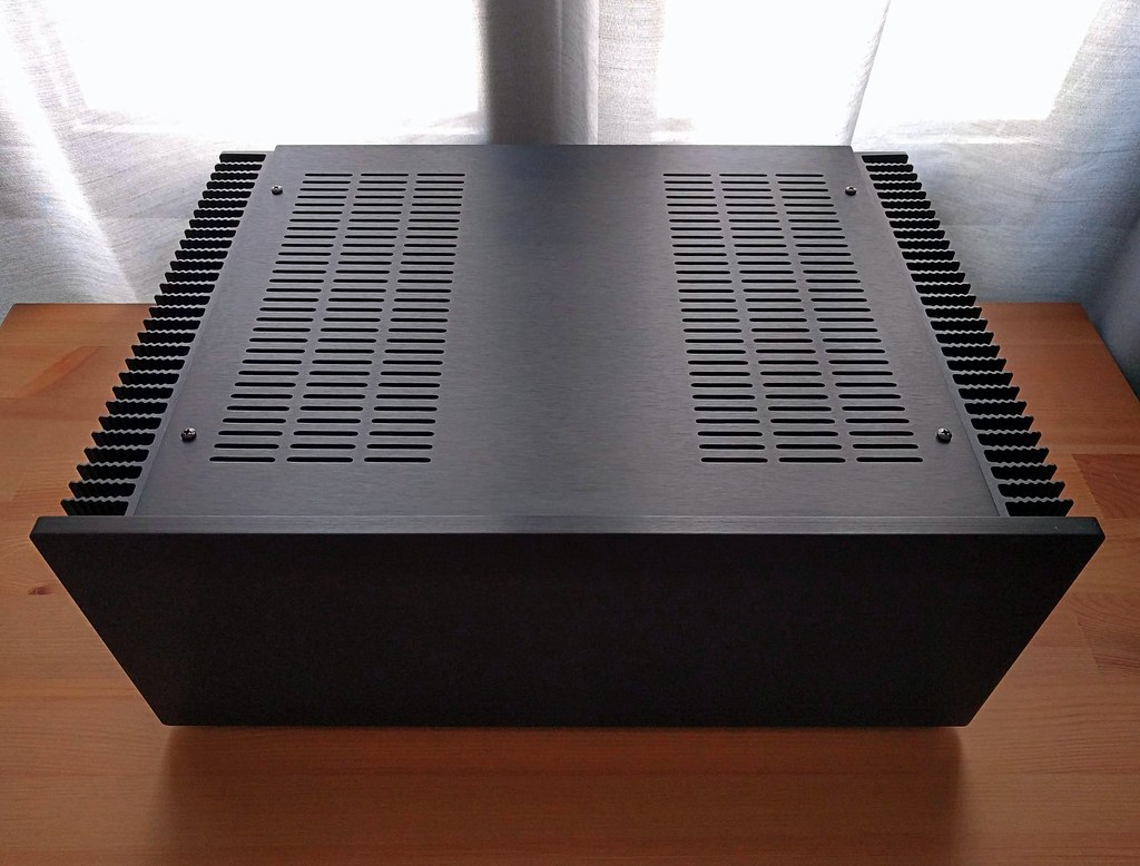
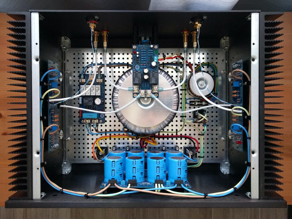
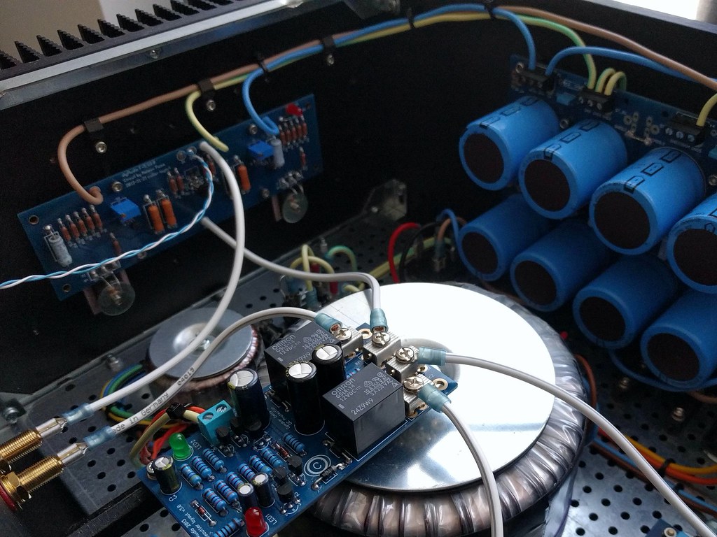
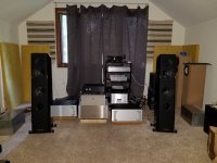
F5 finished this week. More info in this other thread. More photos in higher resolution here. Includes soft start and speaker protection (DiyAudio store) and some custom designed and 3D printed brackets!


amazing work. what is the correct size for those fast on connectors that you have used on the ground loop breaking rectifier diode bridge? i am building one but the connectorsd that i have are the wrong size?
I agree... that shat is art. 😉 The generic case doesn't do it justice... I suggest you get some glass or something so you can see in the biatch.
Last edited:
to EUVL / Patrick #5241/5242
Hello Patrick,
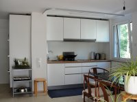
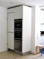
cool idea to use those aluminum extrusions/profiles to build a kitchen. 😉
I made a workbench out of these. But you can use those profiles in so many ways.
Your idea to build an amp as an electrostatic driver is very interesting.
Very high voltage necessary - not for all do-it-yourselfers? 🙄
Greets
Dirk
Hello Patrick,
cool idea to use those aluminum extrusions/profiles to build a kitchen. 😉
I made a workbench out of these. But you can use those profiles in so many ways.
Your idea to build an amp as an electrostatic driver is very interesting.
Very high voltage necessary - not for all do-it-yourselfers? 🙄
Greets
Dirk
Any tube amp is high voltage.
But yes, it is a totally different type of DIY experience.
I am also learning a lot.
John Curl's Blowtorch preamplifier part III
And you will need SJEP170R550 for that Pass STAT circuit to drive loudspeakers.
Will keep you busy for a few years.
Patrick
But yes, it is a totally different type of DIY experience.
I am also learning a lot.
John Curl's Blowtorch preamplifier part III
And you will need SJEP170R550 for that Pass STAT circuit to drive loudspeakers.
Will keep you busy for a few years.
Patrick
amazing work. what is the correct size for those fast on connectors that you have used on the ground loop breaking rectifier diode bridge? i am building one but the connectorsd that i have are the wrong size?
I selected terminal connectors by using a caliper to measure the blades (this was my first build and I didn't know what I was doing). My diode bridges have blades that are ~6.2mm x ~0.8mm so I chose 250 Faston and they seem perfect. I had to use 2 other sizes for this build, as well as ring terminals. The smaller sizes were for the IEC inlet ground (110 Faston) and the power switch (187 Faston).
I still haven't been able to find an economical way to buy star washers for the chassis ground! Seems like I can buy a cheap small bag and then pay $$$ for shipping, or buy a giant kit of multiple sizes for $$$ and free shipping. I just need like 2 of them! 🙂
Last edited:
I agree... that shat is art. 😉 The generic case doesn't do it justice... I suggest you get some glass or something so you can see in the biatch.
Thanks! I don't mind not seeing the guts and I actually wanted it to be really simple and understated outside (why I picked the black faceplate). I kind of like that in some amps (e.g. Yamaha A-S1000, Sansui AU-717) they hide some really nice craftsmanship inside that most people never see.
Last edited:
Thanks! I don't mind not seeing the guts and I actually wanted it to be really simple and understated outside (why I picked the black faceplate). I kind of like that in some amps (e.g. Yamaha A-S1000, Sansui AU-717) they hide some really nice craftsmanship inside that most people never see.
I've been thinking of doing an amp in a glass or plastic case... some cool lighting on various components. I salvaged a huge Plexi table top that is begging to be made into a case. I'm going to let the idea simmer and maybe take it on this winter.
The amp looks great, maybe make a plexi top for it just for when us audiophiles, whatever that is, get together. An amplifier lap dance, look, but no touchy. 😀
An amplifier lap dance, look, but no touchy. 😀

Are you manning the velvet rope for the "champagne room" at BAF?
Are you manning the velvet rope for the "champagne room" at BAF?
Yes, with scantily clad, "Nivana" girls serving wine and cheese!

The Women of BAF
Tend to be younger and prettier than the men. But that is a low bar to clear!
-Tom-
Tend to be younger and prettier than the men. But that is a low bar to clear!
-Tom-
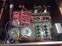
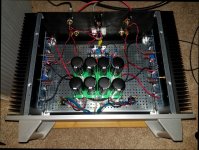
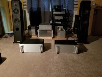
Just another P1.7 finished.🙂🙂
It sounds marvelous, live, it makes me smile.
It sounds marvelous, live, it makes me smile.
Attachments
Last edited:
Just another P1.7 finished.🙂🙂
It sounds marvelous, live, it makes me smile.
"There are many like it, but this one is mine."
SO you see, it's not just another one, it's yours!
JT
Just another P1.7 finished.🙂🙂
It sounds marvelous, live, it makes me smile.
Looks nice. I see the red pre-amp with DIL8 IC's (RIAA ???) PCB's, feeding the second pre-amp stage PCB's (green) which, what it seems, could drive 100dB-efficiency speakers straight, without a need of an output amp🙂
Do you have more details on this P1.7? I can not find any information on the net..? Just curious... I'd like to see the schematics just to know what we are talking about here...
Last edited:
- Home
- Amplifiers
- Pass Labs
- Pictures of your diy Pass amplifier