That's a fantastic looking build! Very tidy and well thought out.
Two questions:
- I considered making my Korg NuTube visible in a way similar to this. I was concerned that the wire leads may cause some issue. You haven't noticed any? Any tips or observations you could share?
- In the second to the last pic in the first post - You seem to be cleaning a part with electrolysis. What part is that in the build?
Hi Fidget and thanks for the compliments.
Initially, I was also concerned that the wire leads could cause an "antenna" effect, or transmit vibrations to the tube, but fortunately this didn't happen, it's absolutely silent, not even a slight uhmm with maximum volume and the ear on the speaker.
I think it's thanks to combination of the shielded transformer, internal aluminum separators and small rubber shock absorbers for fixing the nutube to the front panel, also the chassis is grounded, the pcb and all the input and volume circuit are electrically insulated from the chassis.
The input and output wires have been obtained from a CAT6 network cable as suggested in the forum, those connecting the tube to the pcb are flexible, size 0.4 mm2 (awg 21) from automotive sector.
In the pic of the first post, I was anodizing the input selector knob, after I did the same with the volume one.
Cheers
Cleen work. Congratulations! What does it mean "MK II"? I can't find Q3, R13, R14. And it looks like diodes heatsinks are too small. Have you measured its temperature?
MKII refers to the sound of this amplifier, mark 2 - an improved version.
The diode heatsinks are as per BOM and are perfectly sufficient for the task. I have 2 amps bias per éach amplifier side.
The short circuit parts have been removed, the C1 capacitor is removed, the power supply decoupling capacitors have been chosen for the best sound. In combination with chosen wiring, the power is delivered very fast at the full bandwidth.
The layout provides for the shortest possible wiring.
With C1 replaced with a link, the starting offset (cold) is something like 200mV, which settles within 10 minutes to a range between -20mV and +20mV; however, the turn ON/OFF thumps have pretty much disappeared entirely.
I have modified the circuit diagram, and attached it to my original post, to reflect the mods I did to original Aleph J.
The result is a stunning extension, top and (in particular) bottom. I have never heard better bass control, extension and definition on my 4 - ohm Dynaudio's. Amazing details and a very natural presentation. Very fast transients. Immensely satisfying.
I've been playing with amplifiers all my life, and this Aleph J MKII version is simply without comparison.
Last edited:
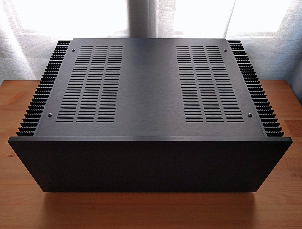
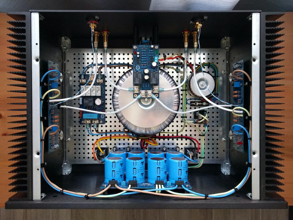
F5 finished this week. More info in this other thread. More photos in higher resolution here. Includes soft start and speaker protection (DiyAudio store) and some custom designed and 3D printed brackets!


Last edited:

Fugly!
(put some plastic cap on that donut screw)
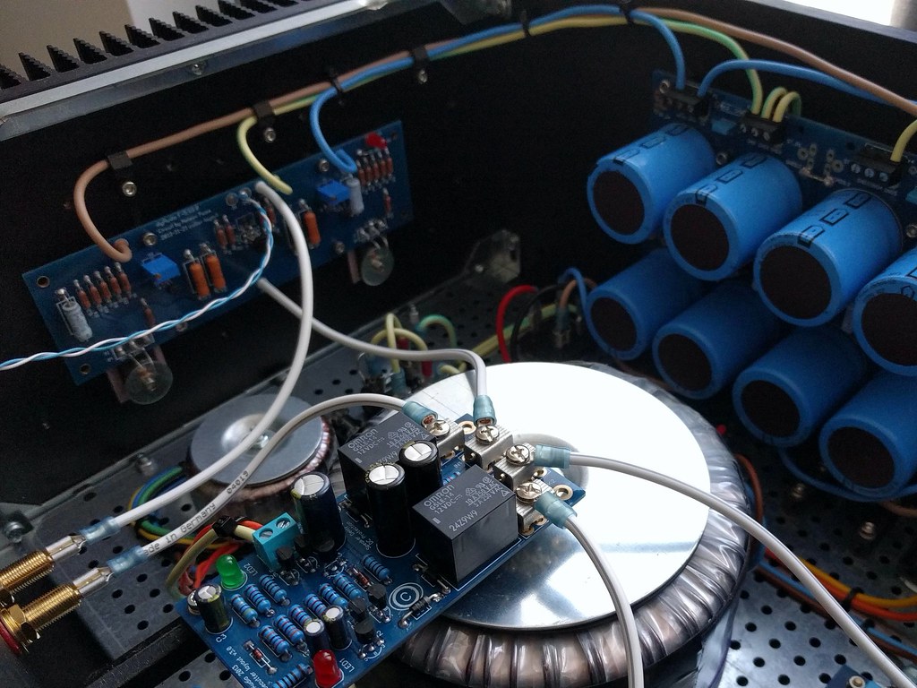
The speaker protection is like a diving board right now (only bolted at one end) so I'm going to make something to clamp on the transformer with posts to hold the other end of the PCB...

just be sure that this what you're going to bolt to xformer screw is not conducting, to avoid possible loop with case
that's dead short
Good point. I wasn't aware of that particular problem!
My plan is to 3D print a cap out of PETG plastic (the same material I used for the other brackets). It will have captive nuts embedded in the posts for supporting the speaker protection PCB, and will clamp onto the transformer nut.
If the transformer causes hum because of the speaker protection board being mounted above I think I can fit a metal transformer enclosure...
@booja30
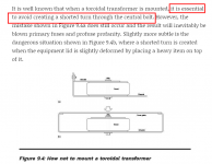
the danger ZM pointed to is not that of a humming ground loop.
a closed loop around an xformer creates a welding tool!!!
ps: very nice build and wiring.
the danger ZM pointed to is not that of a humming ground loop.
a closed loop around an xformer creates a welding tool!!!
ps: very nice build and wiring.
@booja30
the danger ZM pointed to is not that of a humming ground loop.
a closed loop around an xformer creates a welding tool!!!
ps: very nice build and wiring.
When I mentioned hum it was unrelated to the shorting problem. The reason I would consider a metal enclosure for hum issues is that the speaker output cables (and protection board) sit right above the transformer.
BTW I just finished printing a bracket/spacer that will keep the SP board from touching the transformer bracket, even if the amp was dropped! Maybe I'll post a photo of the amended design.
Cheers for the extra word of caution though!
Ok, too late to edit my original post, but here's the new (PETG plastic) part to ensure the speaker protection board (and components) never get close to the transformer mounting hardware. The bracket has captive nylocs in the standoffs, and the screws are only about half the length of the standoff so no chance of them touching the transformer bracket.

An externally hosted image should be here but it was not working when we last tested it.
Last edited:
Thanks everyone! Time to start a preamp project!
BTW, if anyone has an abandoned DCG3/DCSTB lying around they'd sell (unbuilt, unfinished, broken, etc.) I'd be happy to buy it (and forever grateful)!
Last edited:
BTW, if anyone has an abandoned DCG3/DCSTB lying around they'd sell (unbuilt, unfinished, broken, etc.) I'd be happy to buy it (and forever grateful)!
I have a fully built DCG3 one not being used since 6-8 months. Let me know if you are interested in the same.
Thanks
- Home
- Amplifiers
- Pass Labs
- Pictures of your diy Pass amplifier