grataku said:Congratulation on creating this great beast. Way beyond my level of comprehension of electronics but very cool to see implemented by people that know their stuff.
It definitely picks my curiosity in terms of the kind of sound it produces.
I would have been even better if boards were available to make construction a little more accessible.
A question about the output stage, seems to me that paralleling a sufficient amounts of good japanese high power bipolars would have done the trick for any reasonable operation conditions, that is if the amp is stable on reactive loads to begin with. Is the true? Maybe I am not familiar enough with this design.
I often wondered, but never measured, what kind of currents can be achieved by pulsing a few ms into a short before the intrinsic reactance of the PS limits the spike. Has anyone here tried? Is a figure like 50 amp really realistic?
Thanks for your input! Boards are available in Gerber format for downloading - we ordered them from www.4pcb.com under their barebone prototype program. You may order your own boards by sending the downloaded zip file through their web interface.
It is possible to build an EC stage with bipolars, however our design is limited from this perspective. There's a short discussion on the web site about BJTs in our EC stage design.
If I understand correctly your question, no 50A peaks from our EC stage is not realistic, 25A peaks probably is.
syn08 said:
Bob,
While I agree with you that an 8ohm amp should survive 1ohm load chirps, unfortunately the laterals won't make it to 13 amps, not even at the max Vgs of 15V. Though, I'm pretty sure they won't blow (they have Idmax=7A). I have no idea how the chirp distortions could be measured. If you have any information about, I would be happy to give it a try (the spectrum analyzer has chirp output features) and push the amp as much as possible.
To safely deliver 40A of chirp current, my estimate is a minimum of 5 lateral devices, or a total of 10 per channel. As I've already mentioned, this is not practical (matching starts to be an issue) and neither economical (laterals are about twice the price of Fairchild verticals).
Could you provide a link for your protection schematic? Thanks!
I understand about the high current limitation of your devices, and have no problem with the fact that they might not be able to deliver a burst into 0ne ohm.
I have not yet posted a schematic of my protection circuit, but I'll see if I can post something on it this week.
Cheers,
Bob
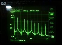
Odd 60 Hz harmonics
A quote from our site:
The spikes around the 1KHz peak are 60Hz mains frequency odd harmonics (120Hz spaced) of unknown origin. They extend into the KHz range. The origin of these mains harmonics needs further investigations. At this point, we suspect a DC imbalance in the transformer core, or a magnetic field (radiated from the toroidal mains transformer) induction effect in the amp wiring.
We did two experiments. First, we build a current loop (which is actually a bobbin of thin magnet wire), fed the signal in an AD797 opamp set for gain of 100 and connected the opamp output to the spectrum analyzer channel. We snooped around with the power amp on, at various output power levels. We were unable to detect any significant 60Hz harmonics other than the 2nd and the 3rd.
Which left the other hypothesis to be verified. We replaced the 650W toroid with two 245W (nominal) toroids having split secondaries (one for each channel, the old 650W toroid had a tap secondary) and slightly higher voltage (2x43Veff). Each amp channel is now fed through two 35A bridge rectifiers and two 50,000uF @60V Sprague electrolytics. The new toroids easily delivered 350W of power, without any significant heating due to copper or core losses), so a clean 200W into 4ohm was obtained.
This kind of setup with separate toroids and rectifying/filtering units is certainly helping in maximizing the crosstalk performance. We did not do so far any crosstalk measurements on the stereo amp but we do know from simulations that our amp could be sensitive to such, due to a relatively poor PSRR of the power ground.
The good news is that the new toroids (made in Plitron) and the new power supply setup made the strange 60Hz odd harmonics almost vanish in the noise floor, at -140dB. Therefore, I think the problem with the tapped toroid was indeed an DC imbalance in the core, perhaps due to slightly asymetrical windings. The core non-linearities helped generating the harmonics, while these harmonics (attenuated by the PSRR) entered the amp, most likely through the power ground connection.
The odd harmonics were originally at around -120dB, so that was not really a tough performance issue. However, we think this is a mechanism that should be taken into account when building amps under 1ppm THD. The quality of the power transformer may impact the performance is unexpected ways. Coincidentally, this would also address Bob's concerns posted here: http://www.diyaudio.com/forums/showthread.php?postid=1330879#post1330879
We will update our web site ASAP.
Bob Cordell said:
Although there are some pretty good electrolytics out there, there is enough anecdotal information on capacitors so as to avoid electrolytics. (...) My view is that if you believe that capacitors in the signal path can make a difference, then you virtually never put an electrolytic in the signal path.
Bob,
I am pretty sure you noticed that all capacitors under 1000pF are, in our implementation, ceramic NP0. All capacitors up to 10nF are polyprop while decouplings are metal stacked. Based on the current results, I think we can safely assume that ceramic caps are as good as any other poly-x. There's only one think that we are unable to estimate, that is the impact of mechanical vibration on the amp output. While this could be a measurable effect, I think we can agree that at least in a power amp this effect is negligible.
Which leaves the question about electrolytics in the signal path (again I assume you have no issue with electrolytics for decoupling). We took the time (due to the low speed this was an overnight measurement) and determined the spectra plus estimating the THD at a low frequency of 10Hz. This was chosen only because it's the lowest frequency that the Amber 5500 can deliver and measure at. Standard measurement conditions, (200W/4ohm, etc...) were used, the only difference is the new power supply, as per my previous message. The new power supply almost completely eliminated the annoying 60Hz harmonics.
Take a look at the attached measured spectrum. While the LF harmonics distribution is clearly different to the HF distribution (all harmonics up to the 10th or so are more or less contributing to the THD), the absolute levels are much lower than the HF spectral components of the same order, which keeps the overall THD still under 1ppm. All we can say is that indeed the THD is slightly larger than at 1KHz.
Given these results, I think we can safely disregard any kind of anectodal information Re: capacitors in the signal path, at least for power amplifiers. If somebody is able to come up with some evidence that a DC blocking electrolytic capacitor (of good quality) in the FB loop is in any way, shape of form inferior to an opamp based servo, please speak up.
We will update the web site as soon as we're done with all the new measurements and interpretations.
Attachments
caps are an issue at ppm distortion levels, generalities are a guide but differing manufacturers examples of the same generic type may differ by enough to reverse some of the rankings - certainly if you believe DA and distortion are linked, just look at Pease' Capacitor Soakage plot of DA for various manufacture caps of the same dielectric
I have personally measured distortion in both coupling electrolytics in CDP and np0 in a 40 KHz active filter
The DC blocking C of a Sony 5.1 ch SACD player front R/L channels are Nichicon "Muse Gold” marked caps, the surround ch DAC output Caps are "lesser" Nichicon Caps
The "Muse" Caps showed higher harmonics of a 20 Hz test signal than the other channels - with the Caps being the only circuit difference I see on the schematic - SACD test disc, Lynx Studio soundcard
In pursuing low distortion composite op amp circuits I made a Av +4 Headphone/line driver amp with a Sallen-Key 2nd order Butterworth low pass filter with a 40 KHz corner
I used 200 V np0 caps - in fact I had 2 in series to get one of the needed values, 1 KHz IMD from 1:1 19/20 KHz was ~ -110 dB with 8 Vpk output, I changed the caps to polystyrene and the 1 KHz IMD disappeared into a ~ 150 dB measurement noise floor
My conclusion is that np0 is very good but not good enough, depending on circuit location, for sub ppm performance - perhaps other manufacturer's np0 do better but then you need to make the measurements, not rely on the generalization
Al Electrolytics can be OK but vary, Bateman's measurements point to nonpolar and Higher V rating as better, with series nonpolar being good for blocking multiple V - and Self's supersizing recommendation seems like good advice too - if the C impedance is responsible for a very small fraction of the V drop at audio frequencies then its nonlinearities have less effect
jcx:
This is what I stated:
Given these results, I think we can safely disregard any kind of anectodal information Re: capacitors in the signal path, at least for power amplifiers.
I have no doubts that for active filters, 24bit D/A conversion, line drivers, preamps, etc... the performance impact could be different.
Coincidentally, we are using Nichicon for all electrolytics. As stated on the web site, the DC blocking is rated at 35V non-polar.
If you could post a few more details about your measurements that would be highly appreciated. Could you tell more about the spectral distribution at 20Hz you got? Who was the manufacturer of your NP0 (we are using AVX)? Have you ever tested for piezo effects?
Re: Re: Re: fighting VAS
Hmmm. I would say that in general the specifics of most fully complementary designs in existence are such that VAS fighting is a practical non issue - most have an even higher VAS Zout.
OK, but who is using a crippled VAS? – Also - crippled VAS? Wot dat? 😕
 Oh, Edmondo. Isn’t that exactly what I implied in post #54?
Cool
OK! will do when back at my other puder.....
See Bob's post #118
That may be true, but the ultimate amp shouldn't be flustered by less than ultimate speakers 😀
Cheers,
Glen
Edmond Stuart said:In general, you can't say that VAS fighting is a non-issue, as it depends entirely on the specific design details. When using a heavily downgraded VAS, its obvious that a 'non-VAS' makes it a non-issue. 😉
BTW, the higher VAS-Zo, the lesser 'pole-splitting' by the VAS.
Hmmm. I would say that in general the specifics of most fully complementary designs in existence are such that VAS fighting is a practical non issue - most have an even higher VAS Zout.
Edmond Stuart said:One important reason we opted for a fully complementary topology is that it opens the way to a more powerful VAS, that is, high current drive capability (75mA) and (essentially) no slew rate limiting. Therefor, using crippled VASes makes a fully complementary topology rather pointless..[/B]
OK, but who is using a crippled VAS? – Also - crippled VAS? Wot dat? 😕
Edmond Stuart said:Also, I like to point out that the primary reason for using a common mode control loop (CMCL) was not to solve the fighting VAS issue, rather to ensure a stable DC operating point (combined with high VAS gain).[/B]
Oh, Edmondo. Isn’t that exactly what I implied in post #54?Edmond Stuart said:As for clamping, I'm sure your setup is okay. In our design however, we had to walk a different path, as a simple clamp couldn't cope with the high drive currents of the NDFL stage. As Ovidiu already said "we sweated blood over the clipping circuitry in our amp". Indeed, it was a "tour de force". We finally ended with a "nested clamp". that acts not only on the VAS input, but also on the inverting input of the IPS (see D13,Q27a,D5,R25). Please, compare our clamping behavior with the original one of E.M. Cherry.[/B]
Cool
Edmond Stuart said:
Hi Glen,
Looks good!!!
> can send you another *.asc file.
Yes, please.
Cheers, Edmond.
OK! will do when back at my other puder.....
Edmond Stuart said:This is one of most difficult subjects. I fully agree with you that an amp should withstand an accidental short circuit condition. But why should an amp be capable of driving 1 Ohm, that is, if this amp is designed to drive 4...8 Ohm speakers?
See Bob's post #118
Edmond Stuart said:Speakers, rated at 4 Ohm, which show impedance dips of 1 Ohm or so, should be boycotted, as it is a bloody shame that manufactures of such ill designed stuff, try to burden amp designers with the lack of competence on their side.[/B]
That may be true, but the ultimate amp shouldn't be flustered by less than ultimate speakers 😀
Cheers,
Glen
Your PGP amp results are impressive
but I still believe there is need for caution in using even the "good" np0 ceramic - it simply isn't equal to the better films - polystyrene, as I've seen, and presumably teflon and the better manufacture's polyprop (from Pease DA plots)
If your np0 C impedance is high enough at audio frequencies compared to local feedback R then your application should be fine as your measurements show - in my np0 filter example the test frequencies were at only 2 octaves below the filter corner frequency so the Cap Z was ~ 25% of the filter R – from this I would worry that, for example, a np0 Miller Cdom could set a hard to overcome distortion limit with more conventional design power amp
I'm using PPS film smt caps in my latest Headphone amp for small values but I haven't fully put together a high res distortion measurement system around my ESI Juli@ to verify distortion, the Lynx card was borrowed
As far as I recall the LF Al electro distortion was a few harmonics - 2-4? with rapidly reducing amplitude with order
All caps are microphonic when polarized - I've heard a Mylar wrap-and-fill cap scream in a old tube scope’s dying switching(chopping) supply
Monolithic construction and mechanically stiff dielectric should minimize the effect, as far as I know np0 formulations are not supposed to be piezoelectric, the higher K titanate dielectrics definitely are – I've heard modern very high K smt caps too in switching supplies – the cycle skipping/burst low load operation brought the frequencies down to audio range with a 4.7 uF 0805 ceramic making audible noise which disapeared at higher load
jcx said:
.................
Al Electrolytics can be OK but vary, Bateman's measurements point to nonpolar and Higher V rating as better, with series nonpolar being good for blocking multiple V - and Self's supersizing recommendation seems like good advice too - if the C impedance is responsible for a very small fraction of the V drop at audio frequencies then its nonlinearities have less effect
Hi jcx,
Thanks for your input, in particular your last sentence (put in italics by me), which is very to the point.
BTW, can you be more specific about your less than optimal NP0 caps, i.e. brand, type value etc. ?
Cheers, Edmond.
Capacitors and vibration
I had a thought over the weekend.
Several people have tried, and failed, to measure significant piezoelectric signals from capacitors. This is where a strain in the material results in a voltage. The simplest way to look is just to connect a scope across a sample and tap it with a pair of pliers. This isn't surprising - piezoelectric effects are only possible in materials with certain symmetry groups, and these are not generally used for capacitor dielectrics; the only counter example I can think of is some of the high-K ceramic materials.
Strain modulation of capacitance suffers no such constraints. So if instead of looking a voltage generation at zero bias, we look at voltage variations under bias, we should expect to see something. To take a trivial example, consider an air dielectric capacitor made of metal plates with gaps - like a tuning capacitor. A force applied to this changes the gaps, and hence the capacitance. In solid dielectric cases, the effects should be smaller, but still measurable.
So my proposed test is to connect one end of the cap to bias voltage, the other to earth via a high value resistor (say 1M), and measure the voltage on the resistor if you tap the capacitor.
Re: Re: Re: Re: fighting VAS
Hi Glen,
That's right! Because these designs lacks a CMCL, there are no other means to stabilize the VAS bias than just using a rather low resistor at the VAS input. As a result, the Zout it rather high, also as a result, there ain't no VAS fighting.
BTW, I know of one exception, a couple of years ago I found few schematics in a book, yes, in a book!, without any measures to define the VAS bias current. Do you know who was this a@#%^le ?
Who? I'm afraid you, but don't worry, lots of people are using a crippled VAS. What I mean by crippled? Well, VAS stands for 'Voltage Amplifying Stage' (as you know of course), so if you have nibbled at the gain, I'm calling that, with all respect Sir, a crippled VAS. 🙂
THX!
Hmmm, I'm afraid you have a good point. OTOH, I suppose that people who pay $40000 for less than ultimate speakers don't understand what THD20=1ppm means, so they will never buy our amp. 😀
Cheers, Edmond.
G.Kleinschmidt said:Hmmm. I would say that in general the specifics of most fully complementary designs in existence are such that VAS fighting is a practical non issue - most have an even higher VAS Zout.
Hi Glen,
That's right! Because these designs lacks a CMCL, there are no other means to stabilize the VAS bias than just using a rather low resistor at the VAS input. As a result, the Zout it rather high, also as a result, there ain't no VAS fighting.
BTW, I know of one exception, a couple of years ago I found few schematics in a book, yes, in a book!, without any measures to define the VAS bias current. Do you know who was this a@#%^le ?
OK, but who is using a crippled VAS? – Also - crippled VAS? Wot dat? 😕
Who? I'm afraid you, but don't worry, lots of people are using a crippled VAS. What I mean by crippled? Well, VAS stands for 'Voltage Amplifying Stage' (as you know of course), so if you have nibbled at the gain, I'm calling that, with all respect Sir, a crippled VAS. 🙂
Cool
THX!
That may be true, but the ultimate amp shouldn't be flustered by less than ultimate speakers 😀
Cheers, Glen
Hmmm, I'm afraid you have a good point. OTOH, I suppose that people who pay $40000 for less than ultimate speakers don't understand what THD20=1ppm means, so they will never buy our amp. 😀
Cheers, Edmond.
@PigletsDad:
I don't have a proper example for piezo effects of caps in HiFi-gear, but in guitar amps this is very prominent, at times. Ususally the cathode bypass cap of the input stage is a clear candidate (the neccessary DC-bias condition that you mentioned), given the tremendous overall gain (compared to hifi) of a guitar amp. I once investigated this in detail, mechanically isolating the cap in question completely, by holding it in my hand and connecting it to the circuit via thin pigtailed magnet wire. Even a weak stroke on the cap's edge with a pencil was very audible and was clearly shown on the scope display also. I tested several cap types, lightweight cased film caps being the worst (IIRC) followed by good al-electrolyics and the best perfomer was a heavy tin-foil type.
- Klaus
one could comment on the irony of being concerned about cap microphonics in tube amps...
the caps I found the ~ -110 dB distortion in appear to be Epcos 3.9nF c0g 100 V from Digikey by the parts baggie left in the drawer - possibly others but that's the most likely source I used
Distortion measurement resolution was extended by using Graeme's method of grounding the positive amp input and driving the xfmr isolated pwr amp's gnd with the signal source
The negative amp input/feedback node was amplified by 30x with a opa228 "gnded" to the positive pwr amp input/measurement ground
This gives a single ended amplified version of the error V at the pwr amp's input that was easily put into the Lynx sound card, adding ~ 30 dB gain to the ~ -130 dB spot noise floor of the ADC
I resistor summed single sines from the soundcard R/L ch of the Lynx CS4393 DAC, additional external buffering didn't seem required to avoid any 1 KHz IMD in the source
this method makes 2 assumptions:
essentially perfect feedback divider performance distortionwise
and that input current from the amp input transistor bias variation over the signal common mode doesn't add to input V error - with inverting amp topology or noninverting cascoded or the PGP amp's bootstrap and low feedback resistor impedance this can be pretty true at audio frequencies
jcx said:
Distortion measurement resolution was extended by using Graeme's method of grounding the positive amp input and driving the xfmr isolated pwr amp's gnd with the signal source
Very intersting comments, thanks! I have read about Graeme's method before, but never saw anything in detail. I seem to vaguely recall a patent on a similar topic... Could you point me to some pertinent information about?
Edmond Stuart said:
Hi Glen,
Looks good!!!
> can send you another *.asc file.
Yes, please.
Cheers, Edmond.
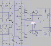
Sorry, didn't get around to it last night.
Here is a higher res jpeg. Voltage clamping on the VAS base and collector. Excess vas current is diverted to ground via a 470 ohm resistor, giving a clipping detection output which will trigger a monostable to flash a front panel LED.
Cheers,
Glen
Attachments
I have Jerald Graeme's "Optimizing Op Amp Performance" book, probably the feb '92 EDN articles cover the same methods but I didn't want to register yet again today to read something on the web
Re: Re: Re: Re: Re: fighting VAS
Well technically it’s the voltage gain of the LTP which is reduced and at least I’m not running a crippled (class AB) output stage 😀
BTW, one of the nicest features of class A is the monotonic-ish reduction in THD with output power level.
Simmed THD-20 into a 4 ohm load for my 300W non-EC TMC amp are as follows:
200W
2.95ppm
100W
1.29ppm
50W
0.65ppm
20W
0.27ppm
10W
0.15ppm
5W
0.09ppm
2W
0.04ppm
1W
0.03ppm
 So wot THD-20 does your amp make at 1W again?
These figures make me almost as giddy as the Rachel Weisz wallpaper on my Windows desktop.
Cheers,
Glen
Edmond Stuart said:Who? I'm afraid you, but don't worry, lots of people are using a crippled VAS. What I mean by crippled? Well, VAS stands for 'Voltage Amplifying Stage' (as you know of course), so if you have nibbled at the gain, I'm calling that, with all respect Sir, a crippled VAS. 🙂
Well technically it’s the voltage gain of the LTP which is reduced and at least I’m not running a crippled (class AB) output stage 😀
BTW, one of the nicest features of class A is the monotonic-ish reduction in THD with output power level.
Simmed THD-20 into a 4 ohm load for my 300W non-EC TMC amp are as follows:
200W
2.95ppm
100W
1.29ppm
50W
0.65ppm
20W
0.27ppm
10W
0.15ppm
5W
0.09ppm
2W
0.04ppm
1W
0.03ppm
So wot THD-20 does your amp make at 1W again? These figures make me almost as giddy as the Rachel Weisz wallpaper on my Windows desktop.
Cheers,
Glen
G.Kleinschmidt said:Sorry, didn't get around to it last night.
Here is a higher res jpeg. Voltage clamping on the VAS base and collector. Excess vas current is diverted to ground via a 470 ohm resistor, giving a clipping detection output which will trigger a monostable to flash a front panel LED.
Cheers,
Glen
Hi Glen,
I see, you have adopted the idea a clipping detection output. Cool.
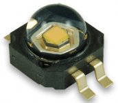
Knowing you like lots of power, what about this LED (see pic) 🙂
BTW, pleeeeeease adjust the drawing options of LTSpice: white background (in stead of gloomy gray) and a larger font.
Cheers, Edmond.
Attachments
Re: Re: Re: Re: Re: Re: fighting VAS
THD20 w/o N = 0.1ppm at 1W.
Cheers, Edmond.
BTW, this wallpaper?
G.Kleinschmidt said:
...................
These figures make me almost as giddy as the Rachel Weisz wallpaper on my Windows desktop.
Cheers,
Glen
THD20 w/o N = 0.1ppm at 1W.
Cheers, Edmond.
BTW, this wallpaper?
Attachments

- Status
- Not open for further replies.
- Home
- Amplifiers
- Solid State
- PGP (Pretty Good Poweramp)