traderbam said:Glen,
Yes the same goes for the pnp dual. Our friends at Analog Devices are somewhat remiss in their datasheet product description where they say "The substrate is clamped to the most negative emitter by the parasitic isolation junction created by the protection diodes. This results in complete isolation between the transistors." It would be more accurate to say that "the two transistors are dc isolated but they have a massive parastic capacitance between them". You'll find it at the bottom of the first electrical characteristics table.
I was caught out by this a few years ago when I was seduced by the convenience of the matched pair part. It wasn't until my frequency response measurements didn't look right that I realised my oversight. In my designs this is a real problem so I don't use these devices. Whether it matters in your circuit is of course for you to determine.
I just thought I'd point it out as you have gone to a lot of trouble to make your sim accurate but I didn't notice this parasitic capacitance in your models.
Brian
traderbam said:Actually, I think it is reasonable to call 35pF massive in a high speed transistor pair; it is half as much again as Cobo after all.
The impact is application specific. And it depends not just on the common mode input signal but also on the loading of the collectors. And the impact is from both the size of the cross-collector current and the non-linearity of this parasitic capacitor.
Brian
I am well aware of the capacitances associated with these devices and that is why I went through some trouble to implement a particularly elaborate bootstrapped cascode arrangement for the MATXX LTP’s as well as an input buffer to provide the LTP’s with a low driving impedance - as you say, the impact of these capacitances is design dependent.
Cheers,
Glen
Okaaayyyyyyyyy..... I just downloaded the complete *.cir spice models for the MATXX devices from Analog Devices.
There is a series pair of back-to-back collector diodes connected as follows: C1-substrate-C2
The models provided for these diodes are:
.MODEL DMAT02 D(IS=1E-14 VJ=0.6 CJO=40E-12)
.MODEL DMAT03 D(IS=1E-14 VJ=0.6 CJO=68E-12)
I have incorporated these diodes in a revised Ltspice design file, which I have attached below (as before, it is an *.asc file renamed with the *.txt extension to allow it to posted as an attachment).
I have also put appropriate drivers (MJE1503X) into the circuit this time and updated the LTP cascode BJT’s to more suitable devices.
The circuit simulates as follows:
THD-20, 150W, 8 ohm = 0.000717%
THD-20, 300W, 4 ohm = 0.000963%
The Class AB bias current is 340mA. 20kHz loop gain is ~34dB.
Here are the driver transistor models:
.MODEL Qmje15033 pnp (IS=7.51228e-10 BF=134.35 NF=1.25737 VAF=12.5778
+IKF=1.88497 ISE=7.74267e-12 NE=3.34528 BR=5.14173
+NR=1.47488 VAR=1.4505 IKR=7.47186 ISC=3.25e-13
+NC=4 RB=4.37743 IRB=0.1 RBM=0.1
+RE=0.000332989 RC=0.381218 XTB=0.223027 XTI=1
+EG=1.05 CJE=3.06005e-09 VJE=0.64838 MJE=0.352991
+TF=4.78203e-09 XTF=1.50001 VTF=1.00006 ITF=0.999988
+CJC=3.00101e-10 VJC=0.600019 MJC=0.409916 XCJC=0.8
+FC=0.534975 CJS=0 VJS=0.75 MJS=0.5
+TR=1e-07 PTF=0 KF=0 AF=1)
.MODEL Qmje15032 npn (IS=3.7344e-10 BF=86.8313 NF=1.23974 VAF=31.5491
+IKF=9.1678 ISE=9.2499e-12 NE=3.28127 BR=5.59346
+NR=1.33161 VAR=2.1791 IKR=5.15023 ISC=4e-13
+NC=4 RB=9.54492 IRB=0.1 RBM=0.1
+RE=0.000568481 RC=0.0931741 XTB=0.737036 XTI=1.04983
+EG=1.206 CJE=3.05969e-09 VJE=0.648491 MJE=0.352663
+TF=4.94819e-09 XTF=1.50001 VTF=1.0001 ITF=0.999982
+CJC=3.00108e-10 VJC=0.600021 MJC=0.40991 XCJC=0.8
+FC=0.534651 CJS=0 VJS=0.75 MJS=0.5
+TR=1e-07 PTF=0 KF=0 AF=1)
Cheers,
Glen
Attachments

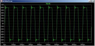
The pulse response is pretty good, Glen. I wonder what the pulse response would look like if you used the same conditions as shown on the PGP website using the same output zoble/filter/load and input as the PGP: 20kHz squarewave, 20Vp-p into 4 ohms || 1uF?
I simulated those back-to-back MAT02 diodes and found them to have 20pF capacitance with zero bias (not strictly necessary I know). This is interesting because AD's datasheet says Ccc is 35pF typical. The MAT03 datasheet doesn't appear to mention Ccc at all.
I simulated those back-to-back MAT02 diodes and found them to have 20pF capacitance with zero bias (not strictly necessary I know). This is interesting because AD's datasheet says Ccc is 35pF typical. The MAT03 datasheet doesn't appear to mention Ccc at all.
traderbam said:The pulse response is pretty good, Glen. I wonder what the pulse response would look like if you used the same conditions as shown on the PGP website using the same output zoble/filter/load and input as the PGP: 20kHz squarewave, 20Vp-p into 4 ohms || 1uF?
I simulated those back-to-back MAT02 diodes and found them to have 20pF capacitance with zero bias (not strictly necessary I know). This is interesting because AD's datasheet says Ccc is 35pF typical. The MAT03 datasheet doesn't appear to mention Ccc at all.
Watch out Brian, you are about to compare Glen's simulations with PGP measurements. Not entirely relevant, isn't it?
Just curious, how did you simulate those two diodes to "20pf with zero bias"? The zero bias collector to substrate capacitance is already set to 68pF in the model.
G.Kleinschmidt said:
I do not disagree that your VAS can be improved with Hawksford cascoding or that doing such would be unreasonably difficult, but I do not think that it can be done with advantage (over the design I have presented) in terms of either performance or complexity – this is especially so at high rail voltages where high VAS currents are used, as there is double the dissipation in your design. And I do think that my VAS topology has an advantage in terms of linearity as it is specifically designed to be wrapped up (along with the output stage) in TMC.
Cheers,
Glen
Hi Glen,
You are right about my VAS taking double the current, all else remaining equal. But I do find it amusing that you of all people would be concerned about power dissipation 🙂.
Note that the larger power dissipation in my VAS does not increase the power/voltage/current handling needs of any individual transistor. The added power dissipation merely results from the fact the the VAS starts out as a differential pair on the top side, rather than a locally single-ended arrangement.
Because I use rather high-input impedance output stages, I usually run my VAS with only 10-20 mA of quiescent current. Bear in mind that my puny little 25 year old 50 watt amplifier did 300 V/us.
So in a 100W amp with boosted 60V VAS rails, my VAS will dissipate a total of about 2.4 watts spread out over mainly four cascode transistors.
In a really big amplifier with 100V boosted VAS rails and 15 mA VAS idle current per leg, the total dissipation would be still only be about 6 watts across mainly four cascode transistors.
My design is also fully compatible with TMC.
Cheers,
Bob
syn08 said:Watch out Brian, you are about to compare Glen's simulations with PGP measurements. Not entirely relevant, isn't it?
I disagree

This is a non-EC amp which only requires minimal output inductance for unconditional stability into a highly capacitive load. So the pulse response will never be matched by any amp with a 2.5uH output inductor.
This is one of the reasons I've decided not to go with EC on the OPS (but I'm only aiming to break 0.001% THD-20 - no free lunch).
syn08 said:Just curious, how did you simulate those two diodes to "20pf with zero bias"? The zero bias collector to substrate capacitance is already set to 68pF in the model. [/B]
I'm guessing that he's talking about the C1-C2 diode capacitance of the MAT02 device. These are 40pF each, so two in series gives you 20pF collector-collector. The pnp MAT03 is 34pF collector-collector.
Cheers,
Glen
Bob Cordell said:
Hi Glen,
You are right about my VAS taking double the current, all else remaining equal. But I do find it amusing that you of all people would be concerned about power dissipation 🙂.
Note that the larger power dissipation in my VAS does not increase the power/voltage/current handling needs of any individual transistor. The added power dissipation merely results from the fact the the VAS starts out as a differential pair on the top side, rather than a locally single-ended arrangement.
Because I use rather high-input impedance output stages, I usually run my VAS with only 10-20 mA of quiescent current. Bear in mind that my puny little 25 year old 50 watt amplifier did 300 V/us.
So in a 100W amp with boosted 60V VAS rails, my VAS will dissipate a total of about 2.4 watts spread out over mainly four cascode transistors.
In a really big amplifier with 100V boosted VAS rails and 15 mA VAS idle current per leg, the total dissipation would be still only be about 6 watts across mainly four cascode transistors.
My design is also fully compatible with TMC.
Cheers,
Bob
Hi Bob
It is not the power dissipation of the VAS that I am concerned with per se; it is the implications imposed by it in terms of complexity and performance by attempting to derive the differential drive signals for a push-pull VAS in a high current amplifying stage.
With regards to slew rate, this is predominantly dictated by the speed of the OPS and the form of frequency compensation employed – there is no inherent slew rate advantage provided by your unipolar input, push-pull VAS topology over either my design or the PGP (for example). My design won’t slew 300V/us because I have chosen TMC for a significant reduction in THD. My class A version is currently simulating 4ppm THD-20 at 300W into 4 ohms with exaggerated base, collector and emitter inductances added to the 40 output devices. This amplifier clearly cannot have an issue in terms of adequate slew rate or TIM performance.
And yes, TMC can be fudged onto just about any topology - with varying degrees of success.
Cheers,
Glen
G.Kleinschmidt said:
Hi Bob
It is not the power dissipation of the VAS that I am concerned with per se; it is the implications imposed by it in terms of complexity and performance by attempting to derive the differential drive signals for a push-pull VAS in a high current amplifying stage.
Cheers,
Glen
Hi Glen,
This is just a bunch of babble.
Cheers,
Bob
Bob Cordell said:
Hi Glen,
This is just a bunch of babble.
Cheers,
Bob
Thanks, but I disagree.
Please post a revision of your LTP based push-pull VAS modified with Hawksford cascoding and TMC and convince me that it has an advantage in any of the following areas:
A) linearity
B) complexity
C) ease of implementation (i.e. board layout, heatsinking dissipating BJT’s, etc)
Cheers,
Glen
G.Kleinschmidt said:
And yes, TMC can be fudged onto just about any topology - with varying degrees of success.
Cheers,
Glen
Hi Glen,
This is another example of you shooting from the hip with another negatively suggestive oblique statement that is not based on detail or knowledge of the implementation. You need to use your imagination a little better.
TMC is essentially just Miller compensation where instead of picking the Miller feedback off of the VAS output, it is picked off of the output stage output and then transitioned to be picked off of the VAS output at higher frequencies, thus enclosing the output stage in the Miller feedback where it is safe. If you understand my favorite kind of feedback compensation (not clear that you do), this hint should be all you need to understand why TMC fits right in.
Bob
Bob Cordell said:
Hi Glen,
This is another example of you shooting from the hip with another negatively suggestive oblique statement that is not based on detail or knowledge of the implementation. You need to use your imagination a little better.
TMC is essentially just Miller compensation where instead of picking the Miller feedback off of the VAS output, it is picked off of the output stage output and then transitioned to be picked off of the VAS output at higher frequencies, thus enclosing the output stage in the Miller feedback where it is safe. If you understand my favorite kind of feedback compensation (not clear that you do), this hint should be all you need to understand why TMC fits right in.
Bob
Sorry, it is a perfectly valid statement. BTW, what we were actually discussing was the merit of the unipolar input Vs fully symmetrical approach and I am glad to see that you have again chosen to avoid addressing the points I have raised in favour of another post of condescending sophistry.
I thank you for the lecture and the hint, but I am well aware of what TMC is, how it works and how to apply it. In fact I have applied it to a design with demonstrable success and gone through some trouble to submit the complete LTspice design file and component models here. Perhaps you missed it.
The key to extracting the greatest advantage from TMC is to make the VAS exceptionally linear. I have done this with Hawksford cascoding on a VAS circuit which I was able to simplify considerably by using a fully symmetrical input stage.
Now I’ll reiterate my previous post to get this discussion back on topic:
Please post a revision of your LTP based push-pull VAS modified with Hawksford cascoding and TMC and convince me that it has an advantage (over the design I have submitted) in any of the following areas:
A) linearity
B) complexity
C) ease of implementation (i.e. board layout, heatsinking dissipating BJT’s, etc)
Thanks.
Hey Edmond.
Forgive me for nagging, but have you had any success yet with simulating a bipolar EC OPS? You said that you were progressing onto this several days ago.
I’m interested because I’m having difficulties finding spice models for decent driver trannies. The On Semi model for the MJE15028, for example, is giving me a Vbe of ~1.7V 😕
Cheers,
Glen
G.Kleinschmidt said:Hey Edmond.
Forgive me for nagging, but have you had any success yet with simulating a bipolar EC OPS? You said that you were progressing onto this several days ago.
I’m interested because I’m having difficulties finding spice models for decent driver trannies. The On Semi model for the MJE15028, for example, is giving me a Vbe of ~1.7V 😕
Cheers,
Glen
Hi Glen,
I'm sorry, I didn't spiced your amp yet due to lack of time and a flu. However, I've successfully spiced another bipolar amp (D. Self's blameless amp) with TMC (5 years ago!).
I know, these ON Semi (=Modpex) models are notorious bad. Regrettably I don't have better MJE15028 models.
BTW, I did a quick sim of Bob's amp with TMC, but the improvement was rather disappointing. For some reason his front end is apparently less suitable for TMC.

Cheers, Edmond.
G.Kleinschmidt said:
Sorry, it is a perfectly valid statement. BTW, what we were actually discussing was the merit of the unipolar input Vs fully symmetrical approach and I am glad to see that you have again chosen to avoid addressing the points I have raised in favour of another post of condescending sophistry.
I thank you for the lecture and the hint, but I am well aware of what TMC is, how it works and how to apply it. In fact I have applied it to a design with demonstrable success and gone through some trouble to submit the complete LTspice design file and component models here. Perhaps you missed it.
The key to extracting the greatest advantage from TMC is to make the VAS exceptionally linear. I have done this with Hawksford cascoding on a VAS circuit which I was able to simplify considerably by using a fully symmetrical input stage.
Now I’ll reiterate my previous post to get this discussion back on topic:
Please post a revision of your LTP based push-pull VAS modified with Hawksford cascoding and TMC and convince me that it has an advantage (over the design I have submitted) in any of the following areas:
A) linearity
B) complexity
C) ease of implementation (i.e. board layout, heatsinking dissipating BJT’s, etc)
Thanks.
Why should I put any effort into convincing you of anything? That is almost always an impossibility.
I'll post my circuits when they are ready, in my own time, certainly not at your behest. I'm very tired of arguing with you.
Bob
Edmond Stuart said:
Hi Glen,
I'm sorry, I didn't spiced your amp yet due to lack of time and a flu. However, I've successfully spiced another bipolar amp (D. Self's blameless amp) with TMC (5 years ago!).
I know, these ON Semi (=Modpex) models are notorious bad. Regrettably I don't have better MJE15028 models.
BTW, I did a quick sim of Bob's amp with TMC, but the improvement was rather disappointing. For some reason his front end is apparently less suitable for TMC.
Cheers, Edmond.
Hi Edmond,
Could you please post that simulation?
Thanks,
Bob
Re: Re: Re: PGP
Hi Ovidiu
In the EC OPS you have the 2N5550/2N5401 as Pre drivers, why?
I'm not to found of that combo...
Why not substitute it for the 2SC3601/2SA1407?
I'm probably missing some thing here...
Super nice work guys!!
// Niclas
syn08 said:
Glen,
Originally, the EC OPS was experimented with 2SC669/2SB649 in the input and EC differential stage and MJE15030/MJE15031 for the driver. With these trannies, the EC OPS performance was (according to our measurements) a little bit better than what Bob reported in 1984, but nothing outstanding. However, to quote from our site:
"It was then a major decision to switch entirely to japanese BJTs. Under these new circumstances, using 2SC3601/2SA1407 in the differential error amp and 2SC5171/2SA1930 in the drivers, the Class AB EC OPS open loop THD-20 (80KHz bandwidth) went down from 0.022% to a reproducible 0.008%, requiring though 0.1% critical components (a few resistors) tolerances."
From 220ppm to 80ppm! "Speed is King" for EC and 2SC3601/2SA1407 (400MHz, Cob=3pF) do fit the bill. To the extend I'm aware of, such devices did not exist back in the early 80's. I don't think we could beat the 1ppm barrier starting with 220ppm open loop THD in the OPS...
Our results in the EC OPS open loop performance were enabled purely by device technology advances. Bob's design is as good today as it was in the early 80's but his results are reflecting the technology status/performance at that moment.
Hi Ovidiu
In the EC OPS you have the 2N5550/2N5401 as Pre drivers, why?
I'm not to found of that combo...
Why not substitute it for the 2SC3601/2SA1407?
I'm probably missing some thing here...
Super nice work guys!!
// Niclas
Re: Re: Re: Re: PGP
Simply because 2N5551/2N5401 is good enough there. I have tried 2SC3601/2SA1407 as well and it doesn't make a wit of measurable performance difference.
2SC3601/2SA1407 is an expensive pair; it costs almost as much as much as a pair of japanese power BJTs and are not very easy to source.
OTOH, a 2N5551/2N5401 pair costs virtually nothing and with Uce=150V, Icmax=600mA, Ft=150MHz and Cob=6pF is one of the few very good low power complementary pairs still manufactured in the States. As a plus, they also come as duals and dual complementary parts (Fairchild, Onsemi, in multichip version SOT363), for e.g. low offset thermal drift differential stages. This pair is by far my favourite for anything but the ultimate performance, where japanese devices rule (see the 2SC2240/2SA970 low noise pair used throughout the front end). I was always thinking how nice it would be to have 2N5551/2N5401 in TO126, to allow a little more power...
Emboss said:
Hi Ovidiu
In the EC OPS you have the 2N5550/2N5401 as Pre drivers, why?
I'm not to found of that combo...
Why not substitute it for the 2SC3601/2SA1407?
I'm probably missing some thing here...
Super nice work guys!!
// Niclas
Simply because 2N5551/2N5401 is good enough there. I have tried 2SC3601/2SA1407 as well and it doesn't make a wit of measurable performance difference.
2SC3601/2SA1407 is an expensive pair; it costs almost as much as much as a pair of japanese power BJTs and are not very easy to source.
OTOH, a 2N5551/2N5401 pair costs virtually nothing and with Uce=150V, Icmax=600mA, Ft=150MHz and Cob=6pF is one of the few very good low power complementary pairs still manufactured in the States. As a plus, they also come as duals and dual complementary parts (Fairchild, Onsemi, in multichip version SOT363), for e.g. low offset thermal drift differential stages. This pair is by far my favourite for anything but the ultimate performance, where japanese devices rule (see the 2SC2240/2SA970 low noise pair used throughout the front end). I was always thinking how nice it would be to have 2N5551/2N5401 in TO126, to allow a little more power...
Bob Cordell said:Hi Edmond,
Could you please post that simulation?
Thanks,
Bob
Hi Glen,
Which amp, of Bob or D.Self? And in which format? As you know, I'm using Micro-Cap, not LTSpice. Or are you only interested in the TDH figures?
Cheers, Edmond.
- Status
- Not open for further replies.
- Home
- Amplifiers
- Solid State
- PGP (Pretty Good Poweramp)