Edmond Stuart said:I have to leave now, but later on I've a look at your design.
Hey, are *.asc files of any use in MicroCap? I can send you the LTspice *.asc file for the amp if you want.
Cheers,
Glen
traderbam said:Ok, I see. You are assuming a 6dB/oct feedback roll-off. Ok.
No, I'm not assuming a roll-off of just 6dB/oct, I'm assuming a roll-off of any rate except zero. That's why your equations are wrong.
You haven't said what the vlaues of H2, H3, etc are. Nevermind.
Of course I haven't provided these figures, are they of any use to someone who's applying incorrect math?
Can you tell me what the actual main fb loop gain is at 20kHz with a 4 ohm load?
Of course I know how large that loop gain is, but...... (you may fill in the rest)
I can estimate the stability margin from your published pulse response.
Brian
If you can, you must be a genius. BTW, what kind of stability margin? Phase margin, gain margin, tolerance against capacitive loads?
Tip of the day: The best way to gather information from us is to share also your knowledge and ideas without any reservations.
G.Kleinschmidt said:Hey, are *.asc files of any use in MicroCap? I can send you the LTspice *.asc file for the amp if you want.
Cheers,
Glen
No, nevertheless send them to me please, so I can look at it by means of LTSpice, which I'm only using as a reader btw. (the jpg image isn't clear enough)
Cheers, Edmond.
darkfenriz said:Nice work!
Congratulations!
Any "special" layout techniques used?
I'm not sure I follow. What layout technique are you referring to? PCB layout?
If so, the only "special" things related to the PCB layout are the top ground plane (not shown in the web site pictures, you need to download and see the Gerbers) connected to the power ground, and a separate signal ground.
G.Kleinschmidt said:OK. The term has be use to describe both things here, and you did actually mention #1, I thought.
I really don't see this as as having to be much of a problem at all. In my design the LTP gains are rather accurately defined/matched by the emitter degeneration and the resistive loads which also serve the purpose of biasing the VAS buffer emitter followers. The VAS gains are accurately matched by virtue of the 100R emitter degeneration resistors and each VAS sees an identical collector load as the collectors are essentially connected together anyway – no gain tracking problems there.
The miller compensation capacitors corner with the resistive load, so the HF roll off of each VAS is accurately defined. So long as the miller compensation caps are matched to 1% or so the HF roll off of each VAS will track quite nicely too.
Not sure that the circulating currents due to gain missmatch will be very high either. A miller compensated VAS can have a very low output impedance at 1MHz and look quite like a voltage source, but what is it at 20kHz? Several k in my design.
Whadda ya think of my CPF Jfet input buffer? for symetrical BJT LTP inputs? 🙂
Consider the merits:
1) Very Low THD
2) Low noise
3) No input resistor bootstrapping required for high input impedance, so no funny LF behaviour.
4) No capacitors (inc big electrolytics) required.
5) No servo required.
6) High Zin
Cheers, Glen
Hi Glen,
Whether you have potential fighting VAS problem I cant say right now, probably not if your are using 0.1% resistors and 1% Miller caps, although I would check it by means of simulation under worst case conditions. Also, don't underestimate the output impedance of the VASes, our amp does 30 Ohm at 20kHz. Several kOhm in your design seems to be a too high estimate. Did you spiced It?
What do I think of your design? Well, generally, it looks sound and clean, although the number of output trannies (40) is rather extreme, but who cares. I've no 'issues' with large numbers as long as they contribute to the performance.
As for 1) Bravo! Maybe you can get an even lower distortion by connecting the right side of TMC caps to the emitter of the pre-driver instead of directly tho the VAS output. This mod unloads the VASes. Spice it and/or make provisions on the PCB for both variants.
One thing I like the most about your design is the fact that low distortion is also possible without EC.
As for 2) It depends whether you can get the right j-fets. Do you have them already? Not to be picky, but I have a serious optical and aesthetic, though inaudible problem with this setup, as the input isn't truly fully complementary 🙂. But don't worry, using D. Self words regarding this topic, "you cannot balance a stage that is already balanced".
As for 3) Initially the LF behavior of our amp wasn't 'funny' at all (i.e. flat), as we planned 20uF in stead of 10uF for the input cap. Regrettable, small pp-caps are no longer available or hard to get.
As for 4) I'm not afraid of good electrolytics and the distortion at LF of our amp is not compromised by this arrangement. Admittedly, it is not the ultimate solution.
As for 5) Indeed, a servo isn't elegant either.
As for 6) I can't deny, that's a nice feature.
Good luck with this beast!
Cheers, Edmond.
Re: Re: Re: Re: Re: Your amplifier
Hi Bob,
And I don't want to rekindle a discussion about any inductance in the output path, so we may just have to agree to disagree with JC. 😀
Cheers, Edmond.
Bob Cordell said:Hi Edmond,
[snip]
Anyway, I don't want to rekindle that coil discussion, so we may just have to agree to disagree on this one.
Cheers, Bob
Hi Bob,
And I don't want to rekindle a discussion about any inductance in the output path, so we may just have to agree to disagree with JC. 😀
Cheers, Edmond.
Edmond Stuart said:
No, nevertheless send them to me please, so I can look at it by means of LTSpice, which I'm only using as a reader btw. (the jpg image isn't clear enough)
No worries. I'll send them tonight when I am back at my other computer.
Edmond Stuart said:Good luck with this beast!
Thanks!.
I just did a quick sim of a VAS to confirm Zout. With an arbitrarily selected 100pF miller cap Zout is about 2k at 20kHz (output droped 6dB with a 2k load).
Cheers,
Glen
Attachments
Edmond Stuart said:What do I think of your design? Well, generally, it looks sound and clean, although the number of output trannies (40) is rather extreme, but who cares. I've no 'issues' with large numbers as long as they contribute to the performance.
It probably is a little OTT, but they are all needed to get rid of the class A heat - 20W per trannie.

Just out of curiosity I ran a 1kHz 300W 4ohm sim - 0.5ppm THD.
Being class A, at lower powers even the THD-20 vanishes well below LTspice's resoultion.
The front end is about as linear as I think I'll bother to make it; the output stage is still the dominant source of distortion. So, adding EC to the OPS should make a significant improvement to the simmed 5ppm THD-20.

I'm currently procrastinating over wheather or not I should bother building it with EC.
Do you forsee any stability quirks with having an EC OPS enclosed in the transitional miller loop?

Cheers,
Glen
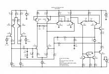
dimitri said:
Sansui AU-X1
Yes, I got the idea for biasing the tail currents of the mirrored LTP's from Sansui's "Diamond Differential Circuit", as used in the AU-X1.
But my complete design is hardly similar to the Sansui circuit, which I attach below:
Attachments
Edmond Stuart said:
Hi Glen,
It seems that there is some confusion about the "fighting VAS' issue. Actually, there are two issues:
1. Stability of the DC operating point (that is what you are referring to, right?)
2. AC common mode currents at higher frequencies, that is what I am referring to.
So I'm afraid we are on cross purposes.
Let me explain why the latter forms a potential problem. As the Miller caps provide local NFB (the higher the frequency, the more FB), the output impedance of each VAS gets quite low at higher frequencies. IOW, the outputs behave more or less as a voltage source.
The output level of each VAS depends on many factors, like the open loop gain of the input stage, gain of the VAS and of course the value of the Miller caps. So, much chance that the individual output levels are not exactly equal, that is, when the outputs are not tied together of course.
As everybody knows, paralleling different voltage sources mean trouble, also in this case. As a result, high common mode currents will circulate, which compromise the performance.
Cheers, Edmond.
Hi Edmond,
This is a good explanation of the "Fighting VAS" concern.
Cheers,
Bob
Bob Cordell said:
Hi Edmond,
This is a good explanation of the "Fighting VAS" concern.
Cheers,
Bob
Thank you Bob!
Cheers, Edmond.
G.Kleinschmidt said:No worries. I'll send them tonight when I am back at my other computer.
Thanks!.
I just did a quick sim of a VAS to confirm Zout. With an arbitrarily selected 100pF miller cap Zout is about 2k at 20kHz (output droped 6dB with a 2k load).
Cheers, Glen
Hi Glen,
I just simmed Zo too and indeed your Zo is ~2k. Admittedly, I didn't expect such high value. The good news is that you don't to have worry much about fighting VASes. Perhaps the bad news is that the potential current gain of VAS is considerable reduced by the 3k input resistor, thus explaining a much higher Zo than in our amp. If the reduced gain of the VAS is really an issue depends of course on many other factors. The only thing that counts is the performance of the amp as a whole.
Cheers, Edmond.
PS: I don't like class-heat 🙂
Hi guys.
I’ve just run a few sims which have convinced me that unless you go to an extreme symmetrical design like Edmond’s which achieves critically low VAS output impedance in the audio spectrum, that “VAS fighting” is a practical non-issue for fully differential designs.
First, I ran a full power ‘perfect’ sim for a reference distortion figure:
THD-20 = 0.000538%
Second, I doubled the value of the emitter degeneration resistors of the lower LTP from 30R to 60R to halve the voltage gain of the lower part of the circuit.
THD20 = 0.001%
Thirdly, I doubled the value of the emitter degeneration resistor of the lower VAS transistor from 100R to 200R, not only dividing by two the voltage gain of the lower half of the circuit again, but also incurring a huge DC biasing error which will be steered by the NFB, causing all the gain stages of the amplifier to run out of balance.
THD-20 = 0.003275%
Fourthly, I increased the miller compensation capacitance of the lower VAS only by 10%.
THD-20 = 0.004553%
That’s almost an order of magnitude worsening in THD performance, but these are obviously quite extreme errors that will never exist in a real implementation of the circuit (unless you had Steevie Wonder load the PCB’s) Real life errors will only incur an extremely small THD increase from optimal.
Edmond, have you still got the simulation files of my 12W amp?
You might want to recreate my experiment.
This is as far as I will look into this tonight. It’s past 11pm and I’m going to bed now.
Cheers,
Glen
Edmond Stuart said:I just simmed Zo too and indeed your Zo is ~2k. Admittedly, I didn't expect such high value. The good news is that you don't to have worry much about fighting VASes. Perhaps the bad news is that the potential current gain of VAS is considerable reduced by the 3k input resistor, thus explaining a much higher Zo than in our amp. If the reduced gain of the VAS is really an issue depends of course on many other factors. The only thing that counts is the performance of the amp as a whole.

I combat the low current gain with an output stage which doesn't require a low driving impedance - hence the tripple EF.
Edmond Stuart said:
PS: I don't like class-heat 🙂
Even in winter? LOL!.
Cheers,
Glen
fighting VAS
Hi Glen,
 Don't take my words the wrong way. Also, our amp has no "critically low VAS output impedance". they behave just as any other normal VAS. So VAS fighting is NOT a non-issue. It's only due to your heavily degenerated VASes that they are too lazy to start a fight anyhow. BTW, how did you know? Looking only at the distortion is not enough, you also have to look at the common mode current.
I've already told you that shunting the VAS input in our design by means of a resistor is unacceptable, as the gain drops too much and distortion rises by more than 20dB (of the front end). Besides, there are more issues at stake. What about slew rate, clipping behavior etc. of your design?
So, It's too early to cry victory.
Cheers, Edmond.
In my
G.Kleinschmidt said:Hi guys.
I’ve just run a few sims which have convinced me that unless you go to an extreme symmetrical design like Edmond’s which achieves critically low VAS output impedance in the audio spectrum, that “VAS fighting” is a practical non-issue for fully differential designs.
[snip]
Cheers, Glen
Hi Glen,
Don't take my words the wrong way. Also, our amp has no "critically low VAS output impedance". they behave just as any other normal VAS. So VAS fighting is NOT a non-issue. It's only due to your heavily degenerated VASes that they are too lazy to start a fight anyhow. BTW, how did you know? Looking only at the distortion is not enough, you also have to look at the common mode current.I've already told you that shunting the VAS input in our design by means of a resistor is unacceptable, as the gain drops too much and distortion rises by more than 20dB (of the front end). Besides, there are more issues at stake. What about slew rate, clipping behavior etc. of your design?
So, It's too early to cry victory.
Cheers, Edmond.
In my
Re: fighting VAS
God knows, we sweated blood over the clipping circuitry in our amp. TMC could be more forgiving WRT clipping behaviour, though.
Edmond Stuart said:
Besides, there are more issues at stake. What about slew rate, clipping behavior etc. of your design?
So, It's too early to cry victory.
God knows, we sweated blood over the clipping circuitry in our amp. TMC could be more forgiving WRT clipping behaviour, though.
G.Kleinschmidt said:
Whadda ya think of my CPF Jfet input buffer? for symetrical BJT LTP inputs? 🙂
Consider the merits:
1) Very Low THD
2) Low noise
3) No input resistor bootstrapping required for high input impedance, so no funny LF behaviour.
4) No capacitors (inc big electrolytics) required.
5) No servo required.
6) High Zin
Cheers,
Glen
Hi Brian,
I like it. It is much the same as the balanced input circuit I have been using for some time that I described over in the Unipolar vs Complementary input stage thread (page 8, post 199).
In that circuit, I used it outside the loop as a differential buffer to provide a nice hi-impedance balanced input for an amplifier. You are using a similar circuit inside the loop to drive the bipolar input stages.
My circuit uses a differential pair to form a differential CFP function. I call the whole thing a Differential Complementary Feedback Quad (DCFQ).
The circuit as shown in the original post along with a VAS to make a balanced input amplifier is shown below.
Being in the open loop, and connected as shown, its THD is less than 0.002% under all input driving conditions.
Cheers,
Bob
Attachments
Re: fighting VAS
Hi Edmond.
Don’t take my words the wrong way either 😉 That wasn't a criticism and I'm not really trying to make an amp that will give lower THD or higher slew rate than yours. In fact I probably won't even add the EC now, as I'm happy enough with the performance.
I agree that just looking at the THD isn't enough to determine if the VAS's are really fighting or not, but the fact that it takes really big errors in voltage gain between the two halves of the circuit to make the THD go up considerably, as far as I'm concerned, for my design, “VAS fighting” is a practical non-issue.
You are trying to get the front end performance an order of magnitude better, your VAS’s have ~100 times lower Zout at 20kHz than mine, and that obviously comes with added difficulties which I don’t necessarily have to worry about in my design – please note; no criticism here.
Slew rate of my amp is what you would expect from a miller compensated amp with 34dB loop gain at 20kHz (I’ll see how much farther I can push this out in the real amp). I could make it higher by using a compensation scheme like that used in Bobs amp, but then I don’t get the OPS THD reduction produced by the TMC.
WRT clipping, I have refined and tested this on the 12W version and it is as good as any amp. I clamp the voltage at the VAS buffer bases to limit the peak VAS current to about 2-3 times the VAS Iq. In this design, I also clamp the voltage swing at the collectors of the VAS with a circuit that tracks the unregulated supply voltage of the OPS. This prevents the VAS trannies from saturating as well as the driver trannies.
Cheers,
Glen
Edmond Stuart said:
Hi Glen,
I've already told you that shunting the VAS input in our design by means of a resistor is unacceptable, as the gain drops too much and distortion rises by more than 20dB (of the front end). Besides, there are more issues at stake. What about slew rate, clipping behavior etc. of your design?
So, It's too early to cry victory.
Hi Edmond.
Don’t take my words the wrong way either 😉 That wasn't a criticism and I'm not really trying to make an amp that will give lower THD or higher slew rate than yours. In fact I probably won't even add the EC now, as I'm happy enough with the performance.
I agree that just looking at the THD isn't enough to determine if the VAS's are really fighting or not, but the fact that it takes really big errors in voltage gain between the two halves of the circuit to make the THD go up considerably, as far as I'm concerned, for my design, “VAS fighting” is a practical non-issue.
You are trying to get the front end performance an order of magnitude better, your VAS’s have ~100 times lower Zout at 20kHz than mine, and that obviously comes with added difficulties which I don’t necessarily have to worry about in my design – please note; no criticism here.
Slew rate of my amp is what you would expect from a miller compensated amp with 34dB loop gain at 20kHz (I’ll see how much farther I can push this out in the real amp). I could make it higher by using a compensation scheme like that used in Bobs amp, but then I don’t get the OPS THD reduction produced by the TMC.
WRT clipping, I have refined and tested this on the 12W version and it is as good as any amp. I clamp the voltage at the VAS buffer bases to limit the peak VAS current to about 2-3 times the VAS Iq. In this design, I also clamp the voltage swing at the collectors of the VAS with a circuit that tracks the unregulated supply voltage of the OPS. This prevents the VAS trannies from saturating as well as the driver trannies.
Cheers,
Glen
- Status
- Not open for further replies.
- Home
- Amplifiers
- Solid State
- PGP (Pretty Good Poweramp)