Clear Plain Polystyrene CCCC test panel (II) :
First plot below is the FDM script output compared to PETTaLS. Note they have in common the modal decomposition. I have prepared in parallel a frequency approach (similar to a classical AC simulation in electronics) but it needs a damping model which is not implemented for now. The problem being to find the good damping model...
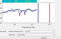
Probably more interesting is the next plot showing the FDM half plane SPL (blue) and the tentative of open back SPL simulation (green) compared to the measurement (orange). The good point is the model is close to the measurement in the low frequencies. There is a few dB error because the modeled back wave is not strong enough. Some analysis to have to patch it? The dipole peak seems to be at work in the 500Hz area. I can say nothing about the difference in the 70 to 300Hz because of more than possible effect of the room. Some outdoor measurements would be welcome.
Next plot is the impedance from the FDM script, similar to PETTaLS one mainly because of the mode decomposition model. A better exciter model with a variable damping should improve it.
Last and I hope not too early in regard to the youth of the open back model is the same panel with the exciter at 50/35% which puts it at 13.5cm from 3 edges the exciter. The model warns about a possible dip at 500Hz due to the acoustic feedback. I can't say it really happens at that frequency but I can say after using this position in directivity tests some months ago that I have in mind it is probably not a so good exciter placement for open back use... The problem with dips is we can't correct them. An EQ can tam the peaks but for the dips? So in a kind of function to evaluate the quality of a design, such dip should probably be severely quoted.


First plot below is the FDM script output compared to PETTaLS. Note they have in common the modal decomposition. I have prepared in parallel a frequency approach (similar to a classical AC simulation in electronics) but it needs a damping model which is not implemented for now. The problem being to find the good damping model...
Probably more interesting is the next plot showing the FDM half plane SPL (blue) and the tentative of open back SPL simulation (green) compared to the measurement (orange). The good point is the model is close to the measurement in the low frequencies. There is a few dB error because the modeled back wave is not strong enough. Some analysis to have to patch it? The dipole peak seems to be at work in the 500Hz area. I can say nothing about the difference in the 70 to 300Hz because of more than possible effect of the room. Some outdoor measurements would be welcome.
Next plot is the impedance from the FDM script, similar to PETTaLS one mainly because of the mode decomposition model. A better exciter model with a variable damping should improve it.
Last and I hope not too early in regard to the youth of the open back model is the same panel with the exciter at 50/35% which puts it at 13.5cm from 3 edges the exciter. The model warns about a possible dip at 500Hz due to the acoustic feedback. I can't say it really happens at that frequency but I can say after using this position in directivity tests some months ago that I have in mind it is probably not a so good exciter placement for open back use... The problem with dips is we can't correct them. An EQ can tam the peaks but for the dips? So in a kind of function to evaluate the quality of a design, such dip should probably be severely quoted.
Christian,Next plot is the impedance from the FDM script, similar to PETTaLS one mainly because of the mode decomposition model. A better exciter model with a variable damping should improve it.
Does your model us a "Q" factor for the panel, like Pettals? Are you using the Pettals value of 10 (from acrylic)? Did you try increasing the Q in the model to see if the predicted impedance comes closer to the measured results?
Did you also measure impedance of the panel in the free (hanging) condition? I'm curious if the impedance peaks look similar, or if they are even sharper in the free condition. I only once ever built a CCCC panel, and it was before I had the impedance rig. I always assumed that a CCCC frame would add damping (even if it wasn't intended), but your measured peaks look remarkably sharp, like I might expect from a free panel.
Eric
Hello EricChristian,
Does your model us a "Q" factor for the panel, like Pettals? Are you using the Pettals value of 10 (from acrylic)?
Yes currently my script is based on a constant Q value, here 10. It is the only model I know currently that gives pretty good results. A simple constant viscous damping for example doesn't give good results. Some variation with the frequency, I guess an increase at low frequency is needed. It is what comes also to simulate correctly the behavior of the exciter spider (visco-elastic damping?). See in my previous posts here the one about the reduction of the peak impedance when we had some mass on the exciter voice coil for parameter extraction.
See the plots belowDid you try increasing the Q in the model to see if the predicted impedance comes closer to the measured results?
The correlation between simulation and measure seems better for the impedance...
But for the FR, I would say it is more difficult. Maybe it is already to late here for me?
I tested different combination of not smoothed/smoothed curves. What gives the best correlation is to introduce smoothing in the simulation output and in the measure. Like if the higher initial damping helped in the reading by a natural smoothing
To be clear, I understood just after the pretty good results of the FDM to get the modes that the damping is as much difficult or even a more difficult topic. This impression may come from the fact I have collected papers about FDM for a long time now, many are available; compared to the papers about damping.
No i didn't measure this panel in FFFF. Unfortunately it is now glued on the frame and I have no more enough material. The IR or the spectrogram show long time ringing in CCCC. So in my opinion it is not a damped design.Did you also measure impedance of the panel in the free (hanging) condition? I'm curious if the impedance peaks look similar, or if they are even sharper in the free condition. I only once ever built a CCCC panel, and it was before I had the impedance rig. I always assumed that a CCCC frame would add damping (even if it wasn't intended), but your measured peaks look remarkably sharp, like I might expect from a free panel.
Eric
FR. greem simulation (OB), orange : REW FR 5ms windowed IR no smoothing

Out of curiosity I did an experiment yesterday where I tested the impedance of the same panel/mounting but with 9 different exciters. I had no particular objective in mind other than to see how similar or different they might be.
The panel in all cases was a 584 x 406 x 5.3 mm three layer balsa "plywood", mounted to a frame using four 18 mm square blocks of Poron 92 foam located at the center of each of the four sides. The exciter in all cases was mounted at the center of the panel.
The results are shown in the plots below. The DAEX25VT-4 is shown as the top trace in both plots, as a kind of reference. Generally, I think it's interesting to see that for the most part the results are pretty similar, especially for all the exciters in the first group, especially between about 100 Hz and about 8kHz. I consider this to be a light to moderately damped panel as many of the impedance peaks are pretty sharp, maybe the differences between exciters would stand out more with an undamped construction.
The second group is a little more varied, especially the Tectonic one (TEAX...).
Any peaks below 30 Hz primarily reflect the exciter "magnet" resonance. the peaks above that are all panel resonances, thought lowest two can be shifted (higher) more or less by the exciter itself. The stuff above 8 kHz perhaps reflects voice coil breakup, at least that is what I have been suspecting.
Eric
It seems the exciters change the first modes, let say below 150Hz probably by their mass and stiffness. Above as you point it there are almost no differences. The frequency of the modes are the same.The results are shown in the plots below. The DAEX25VT-4 is shown as the top trace in both plots, as a kind of reference. Generally, I think it's interesting to see that for the most part the results are pretty similar, especially for all the exciters in the first group, especially between about 100 Hz and about 8kHz. I consider this to be a light to moderately damped panel as many of the impedance peaks are pretty sharp, maybe the differences between exciters would stand out more with an undamped construction.
The second group is a little more varied, especially the Tectonic one (TEAX...).
For the damping, I would look more at the peak values and here the differences are visible above 150Hz.
The TEAX32C30 is an unusual exciter : 10.2g as voice coil mass and 100Hz as blocked coil resonance so a very heavy voice coil (even if the inductance remains classical 0.1mH) and and a light magnet. Its damping is very high also at 2kg/s when usually is more 0.2...
Exactly. And adding the exciter always increases the frequency of those low frequency modes, never decreases. I noticed that first when I was doing tap testing. If I did a tap test with and without an exciter the frequency of the fundamental mode was always higher with the exciter than without, while higher frequency modes were virtually unchanged in frequency. I recall being a little surprised, as I thought the added mass of the exciter would tend to decrease the modal frequency, rather than increase it. But I guess it's more like the exciter spring acts like a stiffener with the mass to back it up.It seems the exciters change the first modes, let say below 150Hz probably by their mass and stiffness. Above as you point it there are almost no differences. The frequency of the modes are the same.
Eric
@EarthTonesElectronics
Dave,
I was interested to see your comments regarding a "single panel, multi-exciter with crossover" DML in the other thread. I was just thinking about playing around with such a system, but now you have me wondering if it's worthwhile. The general tone in the other DML thread is a little toxic, so I thought I'd ask you about it here, I hope you don't mind.
You mentioned that "panels that work well for low frequencies usually don't work well for high frequencies." Can you comment a little more on that? I've thought that a panel that works well for the highs simply needs to be made large enough to also be good at the lows. Is it not so? What do you consider an example of a panel that works good for the highs, and another that works good for lows? Or better yet, what are the characteristics that make a panel good for highs, and what panel characteristics are good for lows?
You also mentioned that exciters for the high end tend be able to handle only 1-5 Watt. But what about the Xcite 19 mm one, that's rated for 20W? Seem to me a pretty good option, possibly? Or do you not think so? Also, highs require a lot less power, right? Isn't 20 Watts a lot, when it only doing say, 1kHz and higher? Or maybe even 5 kHz and up?
One of the concepts that I was thinking to explore was to use multiple exciters (like the 4x pattern here) for the low range, combined with a single exciter for the high range. The idea being to get the smooth low end response from the 4x pattern, but crossing to the "high" exciter at somewhere between 1 and 5 kHz, before the comb filtering from the multiple "low exciters" starts becoming more apparent, and taking advantage of the smaller voice coil of the "high" exciter.
Would it be a waste of effort?
Thanks,
Eric
It is what I have seen with simulation too, in the lows, the main change comes from the exciter stiffness.Exactly. And adding the exciter always increases the frequency of those low frequency modes, never decreases. I noticed that first when I was doing tap testing. If I did a tap test with and without an exciter the frequency of the fundamental mode was always higher with the exciter than without, while higher frequency modes were virtually unchanged in frequency. I recall being a little surprised, as I thought the added mass of the exciter would tend to decrease the modal frequency, rather than increase it. But I guess it's more like the exciter spring acts like a stiffener with the mass to back it up.
Eric
If it is confirmed that the modes above the 1st one(s?) are not changed by the exciter, it could be interesting with the content of the paper below to extract the panel characteristics from the impedance measurements.
A method to estimate the rectangular orthotropic plate elastic constants using least-squares and Chladni patterns
The main "claim" from the paper is for given boundaries conditions and for a panel ratio, the modes are a linear combination of the different bending stiffnesses thanks to coefficients a, b, c related to each modes (rho density, h thickness, A area)
The coefficients a, b, c can be derive from simulation using a set of Dx, Dy, Ds and making some variations around their values (ie 20%?). Dx, Dy, Ds are the inputs of the simulations, the mode frequencies the output. The system of equations in a, b, c can be solved for each modes of interest.
Coming back to the impedance measurements, a, b, and are known from the step before. The modes frequencies are the peaks of the impedance curve. Dx, Dy, Ds might be derived from that.
The key point is to be able to select the right peaks and to name them in mode numbers.
An other conditions is to have a mode simulation supporting orthotropic materials. The FDM script is supposed to do it... Is it possible also with Lisa?
Christian
I only skimmed the paper but it seems to work well. The premise sounds reasonable and seems closely related to the impulse excitation technique for free plates that I use.A method to estimate the rectangular orthotropic plate elastic constants using least-squares and Chladni patterns
The main "claim" from the paper is for given boundaries conditions and for a panel ratio, the modes are a linear combination of the different bending stiffnesses thanks to coefficients a, b, c related to each modes (rho density, h thickness, A area)
Yep, LISA can model orthotropic materials, and it's what I use to extract the material constants from my tap tests. I don't have a rigorous methodology for converging on the best solution, I just use trial and error selection of the elastic properties until the fit of the tap test frequencies and LISA model frequencies are good enough. As they mention in the paper, I use the first three modes to provide the first estimates of G12, E1 and E2, but I usually also look at the next several modes to be sure they also fit well, and may tweak my estimates based on fitting some of the higher modes too, rather than just the first three.An other conditions is to have a mode simulation supporting orthotropic materials. The FDM script is supposed to do it... Is it possible also with Lisa?
Eric
I'm trying to think of a more scientific answer, but until I get to that point, I'll just say that impedance matching says that the heavier, low-frequency exciters are better impedance matched to heavier panels and the lighter, smaller exciters are better impedance matched to lighter panels. You're right, though, that the impedance of a mode is different than the impedance of a panel, and you can scale the modes to impedance match to the exciter (e.g. scale the panel dimensions). I just find that's it's really hard to get any sensitivity out of the little exciters, and I'm talking the really little ones, like DAEX13CT-4. It's certainly not a waste of time to try and design a crossover-based DML system, I think that's an interesting design challenge!You mentioned that "panels that work well for low frequencies usually don't work well for high frequencies." Can you comment a little more on that? I've thought that a panel that works well for the highs simply needs to be made large enough to also be good at the lows. Is it not so? What do you consider an example of a panel that works good for the highs, and another that works good for lows? Or better yet, what are the characteristics that make a panel good for highs, and what panel characteristics are good for lows?
Here's some more interesting stuff -
Surface velocity measurements of my aluminum panel using two exciters (blue) and simulations (orange), and both the average surface velocity and exciter location surface velocity. The small exciter matches up pretty well, but the larger exciter has those discrepancies at higher frequencies. By playing around with numbers, I've determined that the only explanation for this is the voice coil resonances, which interact with the voice coil shape in a pretty weird way. This is also definitely what causes the peak in output at higher frequencies.
My model here doesn't include the voice coil resonances, though I did develop a model that has a single resonance. Most of these exciters have 3-4 extra resonances in the audio range, and it looks like they all need to be included in order to accurately model their effects, which I'm working on!
Christian, Dave,
Below are some impedance measurements I made on the VT25-4, Xcite 25-4 and Xcite32-4 exciters, and using aluminum washers as added masses.
I like the Al washers a little better than the 1 gram plywood weights I used in the measurements I shared with Christian earlier this week. By the time I got 5 of them stacked up the stack was pretty tall (about 15 mm) and I think maybe it was starting to wobble a bit.
The aluminum washers are heavier (2.08 g to be exact), but thinner, so I think the stack is more stable. I tested with 0,1,2 and 3 washers (so 0, 2.08, 4.16, and 6.24 g).
Maybe this data helps you refine (or confirm) your models of these exciters.
REW Mdat files are attached.
Christian,
I also weighed the wood weights in the lab at work and I was amazed at how close they actually were to 1 gram each. Each of the 5 were between 1.01 and 1.02 grams!
Eric
Attachments
Yes, very interesting!Most of these exciters have 3-4 extra resonances in the audio range, and it looks like they all need to be included in order to accurately model their effects,
Could you tell us more about the origin of those resonances? Their frequencies? Thanks!
Christian
Well, they're voice-coil breakup modes - the frequencies seem to be variable, but usually above 5k. The exciters with the coupling discs are the worst (as I wrote about in my paper from earlier this year).Could you tell us more about the origin of those resonances? Their frequencies? Thanks!
I've added the single resonance into my code, and the velocity/SPL results look good. The impedance isn't coming out right, though, and it might take me time to work those bugs out.
Here's a simulation using the EX32FHE2-4 exciter with the plastic disc that resonates like crazy.
Hello Dave,The exciters with the coupling discs are the worst (as I wrote about in my paper from earlier this year).
It is something I didn't have in mind... There is one hypothesis in our small world of DIYer about those kind of peak which is a resonance of the panel within the ring limit and in an other hand behind voice coil break-up there is what was published by B Zenker about some deformation of the voice coil and with as countermeasure a reinforcement of the voice coil. If I remember well he shown a cross shape part.
The disc coupling is in my understanding (I don't have this kind of exciter) something rigid. So how it can be a source of "break up"? Is there a problem with a small gap with the removable part?
In the 5 to 20k range, the electrical impedance increases due to the inductance and in parallel the "mechanical events" are less visible with the increase of the frequency. Is there still something to see of those breakups in the impedance?I've added the single resonance into my code, and the velocity/SPL results look good. The impedance isn't coming out right, though,
Christian
I got the impedance part worked out - this is DAEX25FHE2-4, again, on the aluminum panel.In the 5 to 20k range, the electrical impedance increases due to the inductance and in parallel the "mechanical events" are less visible with the increase of the frequency. Is there still something to see of those breakups in the impedance?
Velocity is looking better, too, but still not exactly right.
From the model I developed that works to accurately predict these effects, it's due to both the ring shape and the breakup modes. The correct form for the velocity output is dependent on getting both the ring shape right and the breakup modes modeled correctly - if either of these aren't right, the results are way off. I also don't know right now exactly what the breakup modes are, to be honest. The most interesting part to me is that they're most prominently measurable when the voice coil is fixed, and this isn't due to a gap or anything like that - there's an extra resonator that's physically in between the voice coil and the magnet, which is still there when the voice coil is completely fixed. I'm sure I'll be able to provide more information as soon as I do more measurements and have some time to think about it.There is one hypothesis in our small world of DIYer about those kind of peak which is a resonance of the panel within the ring limit and in an other hand behind voice coil break-up there is what was published by B Zenker about some deformation of the voice coil and with as countermeasure a reinforcement of the voice coil.
Some exciters, like the EP-4, clearly have multiple breakup modes. I modeled one of them and it makes the results look more like what I had measured, but the frequency is off by a little bit (see graphs below). This is just going to be a number crunching exercise, probably, because it's dependent on matching up a bunch of parameters to both the impedance measurements and the velocity measurements.
Maybe something like these?I also don't know right now exactly what the breakup modes are, to be honest.
Eric


Yeah, I'm sure those are part of it! The weird thing is that I would expect to see a series of resonances from those types of modes, and while I do see a series of small peaks in some voice coil impedance measurements, they don't seem to affect the response much. However, there does seem to be one big mode of a different electromechanical form that much more significantly affects the output, and I'm not sure how this one relates to the series of smaller insignificant peaks. It also doesn't always show up in the impedance measurements as a significant peak. I've only modeled the one big mode for now - it seems to be working pretty well...Maybe something like these?
A big takeaway from this modeling exercise so far is that the resonant breakup mode has a similar form for all exciters, but it affects the response differently for coupling discs and coupling rings - the rings have a node at a lower frequency that significantly dampens the breakup, whereas it seems like the disc shape node is usually above the breakup mode and therefore doesn't affect it, at least for every setup I've measured.
I might not be posting as often over the summer from here on out, but I'm still certainly going to be working on this as much as I can!
@EarthTonesElectronics
Hello Dave,
Here are measurements I prepared some time ago but I just did today. There might be interesting in the quest of the HF resonances.
I started from the situation of a DAEX25FHE glued on a 60x60cm (I know strange dimensions but it is before taking any decisions about how to size it) sheet of 9mm Depron (sort of XPS). This panel shows a huge peak at 12k (red curve)
As a countermeasure, I glued a 25mm thin aluminum disc at the exciter location (on the front side to avoid to remove the exciter).
Result the peak is still present but lower in frequency 8k and a loss of HF
 A bit disappointed because this countermeasure worked some months ago with an acrylic panel, I have removed the disc. The panel didn't return in its initial condition because while removing the alu disc, the glue removed also the skin of the Depron, the peak jumped to 9.5kHz
Then I applied the countermeasure recommended by Steve... a small piece of foam inserted in a maybe 2mm or less central hole. Magic! @spedge . Steve, I hope you'll be happy to see your advice applied!

Here the original panel compared to the sponge countermeasure with the IR and a picture

So I don't say there is no exciter breakup topic. Just to show what is the commonly encountered problem. There might be 2 topics in fact, the resonance of the central area occurring mainly with a light material and the voice coil breakup visible with a heavy material.
Christian
PS : all the measurements are gated at 5ms to reject the room.
PS2: I am wondering now what what would be the result thinning the central area... I remember Steve experimented it and I did so on my very first XPS panel. With the right profile, it could act as an acoustic black hole. Some constrained damping layer might be possible in addition...
Hello Dave,
Here are measurements I prepared some time ago but I just did today. There might be interesting in the quest of the HF resonances.
I started from the situation of a DAEX25FHE glued on a 60x60cm (I know strange dimensions but it is before taking any decisions about how to size it) sheet of 9mm Depron (sort of XPS). This panel shows a huge peak at 12k (red curve)
As a countermeasure, I glued a 25mm thin aluminum disc at the exciter location (on the front side to avoid to remove the exciter).
Result the peak is still present but lower in frequency 8k and a loss of HF
Then I applied the countermeasure recommended by Steve... a small piece of foam inserted in a maybe 2mm or less central hole. Magic! @spedge . Steve, I hope you'll be happy to see your advice applied!
Here the original panel compared to the sponge countermeasure with the IR and a picture
So I don't say there is no exciter breakup topic. Just to show what is the commonly encountered problem. There might be 2 topics in fact, the resonance of the central area occurring mainly with a light material and the voice coil breakup visible with a heavy material.
Christian
PS : all the measurements are gated at 5ms to reject the room.
PS2: I am wondering now what what would be the result thinning the central area... I remember Steve experimented it and I did so on my very first XPS panel. With the right profile, it could act as an acoustic black hole. Some constrained damping layer might be possible in addition...
Attachments

- Home
- Loudspeakers
- Full Range
- PETTaLS Flat Panel Speaker Simulation Software