Hello Eric,Christian, in the FDM script, is there a reason that you don't create a clamped boundary simply by forcing the first derivative(s) of the panel deflection to be zero at the edges, rather than adding fixed points?
Yes, the reason is that my idea is to keep the script as close as possible from the reality with only one plate condition (FFFF) and then adding on top of it the "real conditions" by some fixed (SSSS or CCCC) or (not tested) edge points with stiffness and damping or by testing any other fixations that can be described in words of stiffness/damping/mass. It is maybe utopian but it is supposed to mimic what we do : from a plate of given dimensions we use it like that or we add some surrounding or glue it to have it clamped.
I have the feeling this approach is more general than to add different boundary conditions that are more "mathematical tricks" than real conditions.
We saw with the tests in comparison with FEM results it seems to make sense, or that this approach passed at least those few test cases.
From implementation point of view, I mean from the code complexity, it is in addition easier in comparison to add a new specific condition.
Christian
Yes, but there's no difference mathematically! The frame keeps the stands from moving. I just mathematically fix the stands in place.But this means the 'stands' are rigidly fixed to the panel itself, not to a frame???
On the longer dimension.On which dimension did you assume the 0.35?
Oh, yeah, looks like it was set the the 25mm voice coil dimensions in that picture. I was playing around with different numbers. It didn't make much of a difference, anyway.Is there a mistake in your VC foot dimensions for the XT19-4? Seems like the "blue line" should have moved up, like it did for the XT19-8, rather than match the blue line freq for the XT25.
I don't think this comes from the central area - that effect would cause a decrease in SPL at certain frequencies, not an increase. I can see resonances in the voice coil impedance at these frequencies, which is the same effect I saw in the exciters with coupling discs. So that tells me that there's a voice coil breakup mode causing that increase in SPL. I haven't added this effect into my model yet, but I should eventually.
- the 19 to 32mm models show the peak I mentioned before above 10k which identified coming from the central area.
Attachments
Isn't "mathematical tricks" the essence of modelling? 😊I have the feeling this approach is more general than to add different boundary conditions that are more "mathematical tricks" than real conditions.
I do agree it would be nice to have more realistic conditions. Can you remind me of how you simulated "clamped" conditions? I'm not sure if you shared the specifics or not, previously.
Eric
The voice coil break-up is something known here by a publication from B Zenker but which is not for now linked to observations. The DIYers experience is the peak is material dependent. The countermeasures are to increase the damping or the stiffness of the area. It is also in some patents like this one WO2001072086A2 which suggests to increase the stiffness of the area. I have in mind an other one I can't find now which says there is a dip lower in frequency before the peak.I don't think this comes from the central area - that effect would cause a decrease in SPL at certain frequencies, not an increase. I can see resonances in the voice coil impedance at these frequencies, which is the same effect I saw in the exciters with coupling discs. So that tells me that there's a voice coil breakup mode causing that increase in SPL. I haven't added this effect into my model yet, but I should eventually.
The peak is maybe the result of several parameters?
The level of trick can go from the use of well admitted physical laws to the use of heuristicsIsn't "mathematical tricks" the essence of modelling?
The script has only one stiffness matrix which is the FFFF boundary conditions. On top of that in the system matrix where stiffness, damping and mass are combined, the displacement of any point of the panel can be forced to 0. For the SSSS, this condition is applied to the points at the edge of the panel. For CCCC their neighbors receive also a zero displacement condition. The distance between them is the mesh step which is usually 10mm so I hope something close to a panel glued on a 10mm frame.I do agree it would be nice to have more realistic conditions. Can you remind me of how you simulated "clamped" conditions? I'm not sure if you shared the specifics or not, previously.
To implement the classical approach of SSSS or CCCC would need variants of the stiffness matrix which embedded in my implementation the boundary conditions. Where it becomes very long to implement is the points at the edges, the corners or near of them need specific local matrices (stencil in the FDM vocabulary) which depend of the edge type and in the corner area of the 2 edges (FF, FC, FS...). So the use of fixed points limits the quantity of stencils.
In addition there is no necessity those points are fixed. They can receive a local damping and/or stiffness hoping it can described a surrounding foam or tape... if we know to put figures on it!
In the plots below, the points of the grid are the blue dots (mesh). The blue line shows the panel edges. The points where the exciter force is applied are in red and the fixed points are the blue X. The yellow X are fictitious points in my tentative to take into account the back side in the SPL calculation (similar to edge diffraction models for cabinets or open baffle response... or suppose to be)
Yes... But surely in that case you're fixing them rigidly to the panel which removes the effect of flexible mounting of the panel at each of these points, which is not how panels are constructed, or am I not understanding??Yes, but there's no difference mathematically! The frame keeps the stands from moving. I just mathematically fix the stands in place
Eucy
Eucy,Yes... But surely in that case you're fixing them rigidly to the panel which removes the effect of flexible mounting of the panel at each of these points, which is not how panels are constructed, or am I not understanding??
Eucy
I know you are asking Dave, not me, but can you clarify what it is that doesn't sound quite right to you? What do you mean by "is not how panels are constructed"?
My assumption is that a "stand" in this context implies a point on the panel that has no displacement perpendicular to the face of the panel, but that allows rotation about that point. So it's fixed in the sense of no perpendicular motion, but "flexible" in terms of rotation. I think a small piece of thin foam between the panel and a frame would be approximated by a "stand".
I'm not sure if that clarifies anything for you or not and Dave will have to confirm if this is really what he means by a "stand".
Eric
Christian,To implement the classical approach of SSSS or CCCC would need variants of the stiffness matrix which embedded in my implementation the boundary conditions. Where it becomes very long to implement is the points at the edges, the corners or near of them need specific local matrices (stencil in the FDM vocabulary) which depend of the edge type and in the corner area of the 2 edges (FF, FC, FS...). So the use of fixed points limits the quantity of stencils.
Thanks for the explanation. But I'm not sure I understand yet. I guess I don't know the details behind the "classical approach" of SSSS or CCCC". I would have assumed that the "classical approach" for SSSS would be simply to fix the perimeter points, exactly as I think you seem to have done. And further that the classical approach for CCCC would be to fix both the displacement and the slope at the perimeter points. Is the classical approach deeper than that?
Using two rows of fixed points for CCCC seems like a very reasonable approach too. I might be inclined to add even a third of fourth row, but maybe two is close enough anyway. Are you considering the panel dimensions to be defined by the inner rows, or outer rows, or something between?
In addition there is no necessity those points are fixed. They can receive a local damping and/or stiffness hoping it can described a surrounding foam or tape... if we know to put figures on it!
Yes, it would be nice to have such options.
Eric
Hi Eric....If the stands are heavy pins then in the context of FFFF + stands I see the point (pun intended)...I was conflating the use of foam surrounds with the stands, which wouldn't work as they are fixed inside the foamEucy,
I know you are asking Dave, not me, but can you clarify what it is that doesn't sound quite right to you? What do you mean by "is not how panels are constructed"?
My assumption is that a "stand" in this context implies a point on the panel that has no displacement perpendicular to the face of the panel, but that allows rotation about that point. So it's fixed in the sense of no perpendicular motion, but "flexible" in terms of rotation. I think a small piece of thin foam between the panel and a frame would be approximated by a "stand".
I'm not sure if that clarifies anything for you or not and Dave will have to confirm if this is really what he means by a "stand".
Eric
Eucy
Hello Eric,But I'm not sure I understand yet. I guess I don't know the details behind the "classical approach" of SSSS or CCCC". I would have assumed that the "classical approach" for SSSS would be simply to fix the perimeter points, exactly as I think you seem to have done. And further that the classical approach for CCCC would be to fix both the displacement and the slope at the perimeter points. Is the classical approach deeper than that?
You are right, simply supported (S) is no displacement at the edge points and clamped (C) is no displacement and a null first derivative in the normal direction to the edge.
The principle of the FDM is the displacement of one point is in a linear relation with some of its neighbors. This linear relation is an approximation (finite difference) of the partial derivatives of the equation that describe the problem.
The set of points in relation is named a stencil (see the pictures below)
With this method, a question appears for the points near the edge for which points of the stencil are out of the plate.
The boundary conditions are then used to replace the outside points thanks to the additional conditions of the boundary.
For S or C condition it add +/-1 at the central cell coefficient of the stencil.
For F, there are more sub-cases as the edge points are not set to 0
Generally in papers dealing with such topic, the boundary conditions are used at this level with a diversity of stencils.
My choice is to use only the FFFF stencils and to set the displacement to 0 by an other way, the null derivative being obtain by 2 zero displacements so not strictly by a direct condition on the derivative.
It is maybe not fully academic but seems efficient enough for our purpose.
In addition simply supported and really clamped are theoretical conditions. I have in mind if possible to implement some stiffness and damping at the fixation points in the hope to come closer to a panel construction.
The figures are from the papers I wrote about FDM and which are stored here : DML Github. For more details see the paper FDM... part1, part1b

This is a good question, and I'm pretty sure I have the answer, but it hasn't been tested yet...Yes... But surely in that case you're fixing them rigidly to the panel which removes the effect of flexible mounting of the panel at each of these points, which is not how panels are constructed, or am I not understanding??
Eucy
When I simulate a "fixed magnet" exciter, I just assume that the magnet mass becomes infinite. The spring and damper elements of the exciter that live in between the now-infinite mass and the panel still influence the behavior of the panel modes, though. This is the same math that I would apply to a frame with a foam surround - an infinite mass coupled to a spring/damper combination that is then attached to the plate.
Aha... There's the answer... Thanks Dave- an infinite mass coupled to a spring/damper combination that is then attached to the plate.
Eucy
Dave,
Eucy's original question was about "stands". I think he had some confusion which is now cleared up, but anyway, can you clarify the meaning of "stands". I have understood them to mean points of zero normal (perpendicular) displacement, but free rotation. Is that correct?
Thanks,
Eric
Eucy's original question was about "stands". I think he had some confusion which is now cleared up, but anyway, can you clarify the meaning of "stands". I have understood them to mean points of zero normal (perpendicular) displacement, but free rotation. Is that correct?
Thanks,
Eric
True, but FFFF is also theoretical, at least here on earth! To be fair, it is certainly true that as many as three edges can be really free, but at least one edge (or corner) needs to be attached to something to keep the speaker off the floor!In addition simply supported and really clamped are theoretical conditions.
I'm not bothered at all if a boundary condition is purely theoretical. I never expect any model to be perfect. The important thing is for the model to indicate if going in a certain direction might be beneficial or not. Sometimes purely theoretical conditions are good, perhaps ideal, in that respect.
Eric
Yes, you are right Eric, FFFF is also theoretical. I see it as a starting point same when a DIYer has the panel in his hands and wondering how to attached it with the possibility to use any points of the panel, not only edges or corner to keep the possibilities as open as possible.True, but FFFF is also theoretical, at least here on earth! To be fair, it is certainly true that as many as three edges can be really free, but at least one edge (or corner) needs to be attached to something to keep the speaker off the floor!
I'm not bothered at all if a boundary condition is purely theoretical. I never expect any model to be perfect. The important thing is for the model to indicate if going in a certain direction might be beneficial or not. Sometimes purely theoretical conditions are good, perhaps ideal, in that respect.
Eric
Yes - they would be "Simply Supported" stands rather than "Clamped" stands, which probably isn't as accurate.Dave,
Eucy's original question was about "stands". I think he had some confusion which is now cleared up, but anyway, can you clarify the meaning of "stands". I have understood them to mean points of zero normal (perpendicular) displacement, but free rotation. Is that correct?
Thanks,
Eric
Christian,not only edges or corner to keep the possibilities as open as possible.
Yes, it is good to keep in mind that that the panel can be supported in places other than the edges.
I just read through your FDM Github paper. Really impressive work.
Eric
Clear Plain Polystyrene CCCC test panel :
Hello,
I have built, measured and made a simulation with PETTaLS of a panel. It is made of a 2.23mm thick (sold for 2.5mm) clear plain polystyrene. My intention was to find acrylic but it wasn't available at the store.
This panel is fully clamped on a wooden frame letting an area 39x27cm. The exciter is a DAEX25FHE at 0.364, 0.359 with a fixed magnet.
For the simulation, I chose acrylic and adjusted the density at 1070kg/m³ (coming from my sample weight) and a DAEX25VT.
Below are the comparisons PETTaLS/REW.
The results are really good not to say excellent!
Note that the FR from the measurements is not a direct REW output but one I cooked from the REW IR using a gammatone filter bank (model of our hearing) and an heuristic of my own for the low frequencies to extent to the lows the quasi-anechoic FR from REW which is truncated below the frequency related to the IR window.
The main differences with PETTals are the HF peak (see posts before) and the low frequency roll off due in my opinion to the open baffle conditions (see the -6dB/oct line)
For the impedance, the peaks are aligned in frequency, not as sharp and high as measured. It seems there is no consequence on the FR which is the most important.
Wow! Those are very impressive results - much better than anything I've built. This is an on-axis SPL measurement, yes?Clear Plain Polystyrene CCCC test panel :
Maybe you've already mentioned this equation, but it seems like this is really good evidence for using a -6dB/octave high-pass filter to estimate the open-back effects, with a cutoff at 343/(2*width) - in this case, 343/(2*0.39) = 440 Hz. I'll program that into the software as an option.
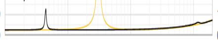
I'm admittedly still confused about that high-frequency peak. In your case it overlaps very well with the coincidence frequency, but that's probably just a fluke (coincidence?). I was able to change the characteristics of that "voice coil breakup" mode in the impedance measurement by using different types of tape to adhere the exciter to the panel/desk, and it did have some small effect on my velocity measurements, but not enough to explain that SPL peak. I'm running a bunch of experiments now to try to get to the bottom of this, and hopefully I can figure it out soon.
Thanks. Yes it is an on-axis SPL at 1m. The walls of the room are far enough to have their reflections after 5ms. I have some absorbent on the floor.Wow! Those are very impressive results - much better than anything I've built. This is an on-axis SPL measurement, yes?
I am not sure it is possible to model the open back effect by a high pass. The open back as 3 effects : a bass roll off at 6dB, a 1st peak when the delay of the back wave is so the return reinforces the front and after a succession of dips and peaks. From measurements, the roll off, the 1st peak and probably one or 2 dips are visible. Or at least I make the assumption the open back is the cause.Maybe you've already mentioned this equation, but it seems like this is really good evidence for using a -6dB/octave high-pass filter to estimate the open-back effects, with a cutoff at 343/(2*width) - in this case, 343/(2*0.39) = 440 Hz. I'll program that into the software as an option.
I am more in the idea of a model based on the distance traveled from the rear to the front. It is coded. I will share results as soon as possible.
Excellent! To see how the tape influence the response is also of 1st interest.I'm admittedly still confused about that high-frequency peak. In your case it overlaps very well with the coincidence frequency, but that's probably just a fluke (coincidence?). I was able to change the characteristics of that "voice coil breakup" mode in the impedance measurement by using different types of tape to adhere the exciter to the panel/desk, and it did have some small effect on my velocity measurements, but not enough to explain that SPL peak. I'm running a bunch of experiments now to try to get to the bottom of this, and hopefully I can figure it out soon.
Christian
PS : the exciter position is suppose to modify the dips (see above the open back topic)
Last edited:
- Home
- Loudspeakers
- Full Range
- PETTaLS Flat Panel Speaker Simulation Software