So, the target for wiring test of resistance in the build doc (pg 14) is 0 Ohms.
Do you mean < 1-2 Ohms on general purpose DMM is Ok?
Will also test continuity for redundancy in testing.
Pull the umbilical so it's 100% not connected to anything. No connections to PCB. The wires on the PCB end should not be touching. You'll want to test to see if there's a short between wires in the XLR.
Measure your + wire to Ground wire. Measure - to GND. + to shield. - to shield. + to -. We're looking to see if any of those connections short out.
In all cases you want to infinite ohms / open connection, some DMM's say "OL".
If you get a reading of 0.0 Ohms, 0.2 Ohms, 1 Ohm, 10 ohms (you get the idea...) - there is a connection that shouldn't be there. You'll need to fix that culprit.
Once you're sure the XLR / umbilical is good, put the connections back in place on the PSU board. Now same test with power off. What do you read for + to GND, - to GND, + to -, etc. You can test from the XLR side if you like. This time you will probably watch the meter act differently as the cap bank starts to pick up some juice from the meter.
The other situation that can be tricky is pin numbering on an XLR for male / female. I always triple check when soldering these up. And the numbering is TINY on them.
Post what you find on that umbilical.

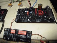
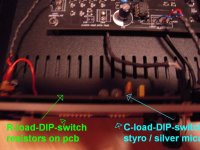
Dirk - can you post a pic of that DIP board and the back of the chassis? Looks like a really clever implementation!!!
Hello PEARL 3-builders,
check my post # 1.896 and post # 1.900 in this thread...
Cheers
Dirk 🙂
check my post # 1.896 and post # 1.900 in this thread...
Cheers
Dirk 🙂
@rthatcher
Revisited my soldering of umbilical cord to XLR and it was a bit sloppy (working too late!) but i did not see a clear short. Added a little electical tape to the + / - pins for additional separation.
Test of umbilical to from female XLR plug to bare wires on PSU side showed 0.0 to 0.1 Ohm and continuity for concordant pins/wires (eg, #2 pin to +/red wire) and OL for other combinations.
After inserting wires into box on PSU board and testing with DMM probe via screws on top of box, the concordant wires / pins read 0.0 to 0.1 Ohms. Discordant pin/wire pairs readings were often unstable, but some readings of OL on repeat testing.
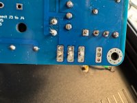
The soldering on the box looks good to me. See pic.
Next?
Revisited my soldering of umbilical cord to XLR and it was a bit sloppy (working too late!) but i did not see a clear short. Added a little electical tape to the + / - pins for additional separation.
Test of umbilical to from female XLR plug to bare wires on PSU side showed 0.0 to 0.1 Ohm and continuity for concordant pins/wires (eg, #2 pin to +/red wire) and OL for other combinations.
After inserting wires into box on PSU board and testing with DMM probe via screws on top of box, the concordant wires / pins read 0.0 to 0.1 Ohms. Discordant pin/wire pairs readings were often unstable, but some readings of OL on repeat testing.
The soldering on the box looks good to me. See pic.
Next?
Attachments
You should measure first between the pins of one end of the completely disconnected umbilical, there should be endless resistance.
Than, measure between the same pins of both ends, there should be zero ohms.
Also to check: pin one of the psu to pin one of the umbilical one end to pin one of the umbilical other end to pin one of the Pearl. Repeat it for every pin. And of course, after the smoke event, check the psu voltages.
Than, measure between the same pins of both ends, there should be zero ohms.
Also to check: pin one of the psu to pin one of the umbilical one end to pin one of the umbilical other end to pin one of the Pearl. Repeat it for every pin. And of course, after the smoke event, check the psu voltages.
Hi All,
before making a next step (and not wanting to make a mistake... again...) a maybe dumb question: How close can two 20VA donuts be placed together? They are fully encapsulated, shielded, etc. ("supreme audio grade", see pic below). I would place them side by side - any issues to expect?
Many thanks!

before making a next step (and not wanting to make a mistake... again...) a maybe dumb question: How close can two 20VA donuts be placed together? They are fully encapsulated, shielded, etc. ("supreme audio grade", see pic below). I would place them side by side - any issues to expect?
Many thanks!
Many thanks!
Okay, I didn't think about gluing them together, but hey, that saves even more space 🙂
An omniunusual suggestion
Okay, I didn't think about gluing them together, but hey, that saves even more space 🙂
An omniunusual suggestion
see here, how to glue them best
Most Greedy Greedy Greedy Boy (of them all)
Yup , that one would be Me , Mighty Moi , ZM
What’s the Catch ?
Nothing …. except here’s the story ……
Culprit : I was constantly bugging Papa about mostly everything , squeezing both question and answer of 42 ….
Consequence : so he in one moment (certainly desperate move ) came to idea that bribe is the way to cope with me ……..
(Fact: Papa is naive ; Do not tell him that simple e-mail addy block is more than sufficient to solve all his ZM related troubles…….. though if he really start using that...
Actually...... This one doesn´t look particularly good 😉The soldering on the box looks good to me. See pic.

Thanks, not what i was referring to, but thanks for the tip and keen eye!
Ok, progress, and next question.
Following rthatcher’s suggestions (and others), my umbilical cord generally checked out and my wiring to the various pins on XLR were correct.
So i tested the PSU with live mains using a cheap variac tonight and got both LEDs lit and about 25-26 V in each rail.
Dies this suggest no damage to parts on the board?
Should i proceed to next set of tests with the P3 elements?
Thanks to all for your input!
Agreed. Assuming voltages at XLR out from PSU are as expected, move on the RIAA box side of the umbilical cord. Is it soldered to phono boards? Simple test is take DMM and measure ohms from “+” on both sides - PSU board out and phono board in. Move on to - and GND. This test should make sure the pin connections are correct at the XLR. Also test for shorts between them. So measure between +/gnd, -/gnd, +/-
Last edited:
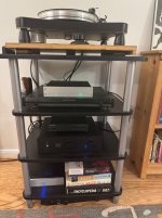
Made a start on the conversion of the Rotel into a Pearl 3. I've chopped the main board down to retain 2 x bulk caps and a couple of resistors. After the bridge there's +/- 30vdc which reduces to +/- 18.6vdc after the resistors that I've kept. That's where I'm planning to take the supply to the boards. I've installed a 12mm thick steel block as a partition between the tranny and the boards to dampen interference. The boards will fit snugly in the rest of the enclosure. It'll be fairly tight but doable. Planning to make a start on building the boards tomorrow...

It lives — and sounds lovely out of the blocks!
Still need to tweak R27 to get it in spec (currently ~2.4V / 10mA). Will it sound even better then?
The green LEDs that came with need a change to Pass blue.
Thanks to all for your much needed help/support, in addition to Wayne’s huge generosity.
So much fun, when the smoke clears.
Chuck
Still need to tweak R27 to get it in spec (currently ~2.4V / 10mA). Will it sound even better then?
The green LEDs that came with need a change to Pass blue.
Thanks to all for your much needed help/support, in addition to Wayne’s huge generosity.
So much fun, when the smoke clears.
Chuck
Attachments
It lives — and sounds lovely out of the blocks!
Once it has broken in for a bit, I'll be interested to hear your take on how it compares to your JC3 Jr!
- Home
- Amplifiers
- Pass Labs
- Pearl 3 Burning Amp 2023