As the P3 has a pair of regs and a cap multiplier on the first stage, you are best suited using a plain vanilla supply -- use the trafo, some decent bulk caps, ditch the rest of the stuff.

This is an absolute match made in heaven! Wow @wayne you did a heck of a job on this Pearl3! The old 2a3 never sounded so good! I swear its digging another 10hz deeper now. Dead quiet, amazing detail and clarity. . . just wow! Ended up buying another kit to build for my buddy, he's going to freak when he hears this. Going from a schiit mani > darlington labs MP7 > bottlehead eros > pearl 3, this thing is king of the heap, no doubt at all. Thank you!!!🤘

The missing bits of the schematic on their right side are very important to answer the question… have you got the whole thing?
PSU seemed good, until it wasn’t. Alas.
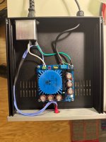
Began assembling the umbilical connector last night.
Prior to putting XLR connector on the PSU was good.
Both LEDs lit and about 26 V in both rails (+/- correct). I let the unit reduce voltage for a few minutes until it was very low.
Next, i added the XLR connector. Was not exactly sure what to do with the shield wire so i soldered it into position #1 on plug. I tested with the female XLR attached to connector with the small wire attached from #1 position to post as described in build guide.
Next, I failed the smoke test when testing just the umbilical (ie, not wired or attached to P3 unit).
Also, the LED on + rail no longer lit and smoke arose from that corner of the board.
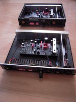
Some pics attached.
Where to begin?
Thanks in advance.
My 6th DIY build and first sign of smoke. Am i in the club now, 😂?
Began assembling the umbilical connector last night.
Prior to putting XLR connector on the PSU was good.
Both LEDs lit and about 26 V in both rails (+/- correct). I let the unit reduce voltage for a few minutes until it was very low.
Next, i added the XLR connector. Was not exactly sure what to do with the shield wire so i soldered it into position #1 on plug. I tested with the female XLR attached to connector with the small wire attached from #1 position to post as described in build guide.
Next, I failed the smoke test when testing just the umbilical (ie, not wired or attached to P3 unit).
Also, the LED on + rail no longer lit and smoke arose from that corner of the board.
Some pics attached.
Where to begin?
Thanks in advance.
My 6th DIY build and first sign of smoke. Am i in the club now, 😂?
Attachments
Chedma.
Can you tell what's blown? What let the smoke out? That's the first thing.
Once that's fixed test without umbilical.
For the umbilical - test for shorts between the wires. Measure ohms wire to wire, or use the continuity buzzer function on your DMM. Since you blew positive rail, i suspect there's an issue positive to ground, but check them all.
Once the PSU and umbilical check out - hook them up.
Before firing it up, test one more time for shorts on the umbilical.
Finally apply power and do a final test for the PSU.
Do all this before hooking up to the RIAA box.
@chedma -
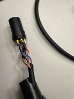
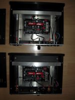
Please let us know your intentions re: each conductor. I can't quite make it out in the photos.
You have 5 conductors in the umbilical: 4 insulated; red, blue, black, clear; and the bare shield.
For pins 1-4, how did you intend to connect them? For the umbilical, please identify the pin # and the color for:
V+ Red? Pin?
V- Black? Pin?
GND - Blue / Clear? Pin?
Shield - Shield? Pin?
Did you validate this with a continuity check at the pins of the XLR? i.e. before powering it up, did you check to ensure that there were no shorts and that from the Euroblock on the PSU to the end of the XLR chain everything was connected as you intended? If not, check now. It's hard to tell in the photo.
Make sure that all pins are properly identified. They should be marked on the case of the XLR components. It's easy to get them reversed. Ask me how I know.
The good news is that everything can be repaired. Remove the umbilical, and identify any burnt components. If you shorted one of the supply rails to GND (seems likely), you can sort that out with some re-work.
Welcome to the club!
And maybe test the umbilical without plugging the XLR plug into the female socket (and before wring pin 1 to the case too, maybe)
And what allinmyhead said... it's easy to confuse pin ID when you're looking form inside out and then outside in.
(Well... that could just be me.)
And what allinmyhead said... it's easy to confuse pin ID when you're looking form inside out and then outside in.
(Well... that could just be me.)
After the transfromer there's a bridge rectifier (with 4 x 0.01uF CAPS) and then what appears to be 2 x Nichicon 4700uF blackgate CAPS before the section with the regulators/diodes. Are you saying to pick up the VDC after the Blackgates but before the regulators?As the P3 has a pair of regs and a cap multiplier on the first stage, you are best suited using a plain vanilla supply -- use the trafo, some decent bulk caps, ditch the rest of the stuff.
Attachments
Thanks all. It’s great to have the cavalry on hand!
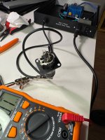
RT,…did not see what released smoke (best guess, 1uF or 220uF caps + rail/LED corner, or something in between). If no visual damage, how can i go about testing (sorry, no experience on that front)?
It was late when smoke appeared, so i cut my losses and went to bed.
This morning i tested ohms (with no power) from box/wires on psu board out to female XLR connect posts and got 0.2 to 0.4 ohms. Is that close enough to 0?
IAIMH…intent for the wiring.
Red + #2 pin
Black - #4 pin
Blue/clear ground #3 pin
Shield (umbilical) #1 pin
I likely shorted something somehow.
Will do more investigating and testing tonight.
Thanks!
Yeah - 0.2 or 0.4 Ohms is close enough to zero on a general purpose DMM. To get precise <1 Ohm readings requires a more expensive unit. For the test you're doing consider anything 1-2 Ohms or less as a short.
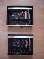
I thought I hook up the the Pearl with just 1 donut and 1 psu board, with wiring of both channels absolutely identical.
The result is the same - slight noise in both channels, but a slight hum in the right channel too... I changed the input and output cables, the sides, everything - and the hum is always associated with the same board.
Connecting the amp to my grounding block brings even stronger hum, almost loud... I'm slowly getting desperate.
Could it be the one board? 🤔
So, the target for wiring test of resistance in the build doc (pg 14) is 0 Ohms.Yeah - 0.2 or 0.4 Ohms is close enough to zero on a general purpose DMM. To get precise <1 Ohm readings requires a more expensive unit. For the test you're doing consider anything 1-2 Ohms or less as a short.
Do you mean < 1-2 Ohms on general purpose DMM is Ok?
Will also test continuity for redundancy in testing.
Taken a few readings from the Rotel PSU section. I seem to be getting +/-30.7VDC immediately after the initial caps (C905/C906) which reduces to +/-18.4VDC after the resistors (R901/902). The voltage after the next section of transistors is then +/- 17VDC which feeds the rest of the board. There's a full schematic and circuit board in the PDF attached...
Attachments
That's exactly what I did now, I swapped the boards 😀@Plott If you've got to ask, you know the answer. I guess the last thing to try is to physically switch the two boards and check the hum goes with the board.
And if you want to keep the noise down, don't connect P3 to your grounding block.
And the hum is still in the right channel.
However, as the donut wasn't fixed, I was able to move it back and forth in the chassis. And lo and behold, when I moved it all the way to the left channel, there was barely any perceptible hum, and on the right channel, - nothing, just noise. Apparently, the donut produces an asymmetrical stray field... Okay, Q.E.D., I'll start working on the external PSU chassis tomorrow 😀 The basic chassis is arrived today from @Gianluca 🙂
Hello Chedma,
I have used Neutrik XLR-4pole-connectors in many of my preamp- / active crossover builds to connect the PSU with the audio circuit.
I never had any issues.
But: I shrinktubed the connectors inside the XLR-plugs and on the XLR-sockets. They are close to each other.
To solder the wires to the XLR-plug-connectors (with shrink tube over the wire) is a pain. Why? The shrinktube gets the heat during soldering. Often it is difficult to push them from the wire over the XLR-solder connector - cause it shrinked slightly.
But it is well worth the effort. In many years I hadn't to repair one of them.
Patience is your friend here... 😉
Cheers
Dirk
Attachments
- Home
- Amplifiers
- Pass Labs
- Pearl 3 Burning Amp 2023