Your feedback loop has an issue here. Between + phono out and the - input of op amp pin 6 should read about 36K Ohms. C8 may have some effect over time so try meter in both directions and let settle.I wasn’t sure if you meant Opamp side A or B so I took both.
Side A
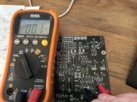
Opamp pin 3 (+IN A) and ground is 0.2 ohm
Between Pin 2 (-IN A) and phono output is 1.02 Mohm
Side B
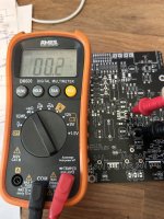
Between pin 5 (+IN B) and ground is 47.4k ohm
Between Pin pin 6 (-IN B) and the phono output it just keeps climbing up and never settles
Is C8 positive supposed to be connected directly to Pin 7?
I’m seeing continuity between C8 + and Pin 7.
The board shows a trace that connects them but the schematic shows C8 connecting only to R18 and C25 only.
I’m seeing continuity between C8 + and Pin 7.
The board shows a trace that connects them but the schematic shows C8 connecting only to R18 and C25 only.
I just checked Pin 6 to Phono out and have approx 35k ohms.Your feedback loop has an issue here. Between + phono out and the - input of op amp pin 6 should read about 36K Ohms. C8 may have some effect over time so try meter in both directions and let settle.

I made the modification
details?
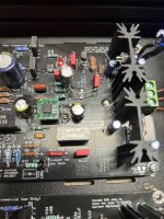
On the boards I bought from another member it looks like there is a trace that connects C8 positive to pin 7. So there is 220 ohms between pin 6 and 7 as well.
I made the below modification. I’ll hook hook everything back up and test it tonight to be sure I have output before confirming that was the exact issue.
I have 3 other pairs of the same boards so I’ll probably try to cut the traces and add jumpers underneath.
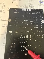
The images above show the continuity and the traces. My red probe at the back of the board is touching C8 positive and you can see it attached to Opamp Pin 7 and then to R25.
I made the below modification. I’ll hook hook everything back up and test it tonight to be sure I have output before confirming that was the exact issue.
I have 3 other pairs of the same boards so I’ll probably try to cut the traces and add jumpers underneath.
The images above show the continuity and the traces. My red probe at the back of the board is touching C8 positive and you can see it attached to Opamp Pin 7 and then to R25.
Attachments

Phono is finally working after a hard week of troubleshooting…
Thanks to everyone for the help tracking down the issue.
All I need to do is replace the standoffs with some plastic ones after noticing a few times it was shorting out to the chassis giving me a weird voltage.
It is much quieter than the first P3 I built.
Thanks to everyone for the help tracking down the issue.
All I need to do is replace the standoffs with some plastic ones after noticing a few times it was shorting out to the chassis giving me a weird voltage.
It is much quieter than the first P3 I built.
Well that explains it not the circuit boards I did.
@Dneu2011 Well done.It is much quieter than the first P3 I built.
To what do you attribute the lower noise? The SB Ver 1.0B PCB? Something else?
presumably others have bought the same boards and used them.
have they all had similar experiences? and solutions?
have they all had similar experiences? and solutions?
Hello,Thanks to everyone for the help tracking down the issue.
Please detail all in a single post what the issue is and what is the solution.
Is it metal standoffs only? Or is it more?
Thanks DT
@Dneu2011
Sorry about my post #2,978.
Got U1A &U1B confused 😊
Funny though...... I have the earlier PCB´s from Sylvain (1.0a), so I went to check the error, you described.
No connection on these boards from C8+ to pin 7.
Try reaching out to @Algar_emi and ask, if the black version boards (mine are red) have this error.
Would be helpful to other members to get this clarified 😉
If you close the RIAA network at the output of U1:B (rather than the junction of R23,R24) you will get a large DC output. I made that mistake when bread-boarding. RIAA compliance, gain, noise etc were fine but large DC on the output.
I have very little DC on the output of my DIYAUDIO Store boards.
I have very little DC on the output of my DIYAUDIO Store boards.
Hi. Thanks Dennis for the findings, and sorry for those that got the ver1.0a pcb. I made some change to the supply trace routing to try to improve the supply and ground layout on this version (the last one). I took great care to double check the changes but it seems i miss this one, sorry. I’ll send the info, and how to correct the pcb before assembly to those that bought this version. Problem had already be corrected on my design file and next pcb won’t have the error.
For those who bought the pcb from me check your email, I’ll send the mods info shorthly.
note: the error was not on the first red pcb version.
sB
For those who bought the pcb from me check your email, I’ll send the mods info shorthly.
note: the error was not on the first red pcb version.
sB
Dneu2011 you can correct the pcb error from under, and resolder the parts at their correct location for a nicer assembled pcb. I will send the info today on how to correct the pcb with two easy steps, done from under the pcb, before or after assembly, to all the member that got the Ver1.0b version.
Please check your private email for details
Sorry again
SB
Please check your private email for details
Sorry again
SB
Last edited:
Hello All,
This PEARL 3 project has become quite the nuanced learning opportunity.
Now we are into "trace cutting" and "green wire repair"
This SB Ver 1.0B PCB is black. I am looking for the darkest shade of CAT 6 wire to make the repair.
Thanks DT
https://learn.sparkfun.com/tutorial...nd-pcb-traces/rerouting-and-green-wire-repair
Interested in purchasing a Pearl 3 full kit or bare boards. If anyone has a lead on this, please advise.
I did sign up for the notification.
I did sign up for the notification.
- Home
- Amplifiers
- Pass Labs
- Pearl 3 Burning Amp 2023