
Your measurement of U1 - 7: 920mv is what I am seeing at the output of my P3 RCAs. I am wondering if maybe the toshibas are bad or even my J112's are at fault. I have measured them multiple times reading 1.92V with a 599 resistor giving me 3.8ma

I am only seeing a few mV to 10mV at most at my RCA jacks. The R23 and R24 resistor voltages are 0.30 and 0.31 that varies some from each other. That's all I see at the RCA output.Your measurement of U1 - 7: 920mv is what I am seeing at the output of my P3 RCAs.
Yea. That's what I figured I should be seeing at the outputs. I will put all my measurements on the schematic tonight and post here.
Here are some measurements I took today and Pin 7 is what stands out most to me...Just took a look at mine, both channels similar. I am using LME49720 opamps and have R27 set to 1k ohm making the current around 3mA for U1 bias current.
U1-1: 12.5mV
U1-2: -0.2mV
U1-3: 0 (grounded)
U1-5: -0.4mV
U1-6: -0.3mV
U1-7: 920mV (0.92V)
The U1:B cct has no DC gain, so U1 pin 6 must be at the same DC potential as the R23/R24 node. So, I'll bet a Loonie ($1 CAD coin) the problem lies in the feedback network.Here are some measurements I took today...
If the feedback network were open, you could get the voltages you report at the output. However, I think I recall you said there was very little gain; so that isn't the problem. A short along the feedback path, either to ground or to U1 pin 7 might provide both the output DC level and the reduced gain.
How could a freak short like that possibly happen to both channels? Must be Oumuamua.
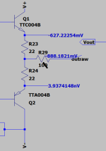
At above schematic:
Are you sure R23 / R24 both are 22R resistors?
Both should have same voltage drop?
Edit: I can see that have......and output state is running at about 13-14 mA bias which is expected.......from memory of my own P3.
Are you sure R23 / R24 both are 22R resistors?
Both should have same voltage drop?
Edit: I can see that have......and output state is running at about 13-14 mA bias which is expected.......from memory of my own P3.
For resistor 23 and 24 I used 21R5 resistors I had on hand and for R15 I used 3.3k (not 3.32k).
Could using these values cause the issue?
Also I should add that I completely disconnected the second channel and have only been troubleshooting one board first.
Could using these values cause the issue?
Also I should add that I completely disconnected the second channel and have only been troubleshooting one board first.
while powered Off - remove OP
measure resistance between OP +IN and GND
measure resistance between OP -IN and preap output
measure resistance between OP +IN and GND
measure resistance between OP -IN and preap output
I wasn’t sure if you meant Opamp side A or B so I took both.
Side A
Opamp pin 3 (+IN A) and ground is 0.2 ohm
Between Pin 2 (-IN A) and phono output is 1.02 Mohm
Side B
Between pin 5 (+IN B) and ground is 47.4k ohm
Between Pin pin 6 (-IN B) and the phono output it just keeps climbing up and never settles
Side A
Opamp pin 3 (+IN A) and ground is 0.2 ohm
Between Pin 2 (-IN A) and phono output is 1.02 Mohm
Side B
Between pin 5 (+IN B) and ground is 47.4k ohm
Between Pin pin 6 (-IN B) and the phono output it just keeps climbing up and never settles
I know, I´m ruining Zen Mod´s wish for your learning abilities 🤣
but 0,2 ohm on +input A means, that it is shorted (should be 47K).
but 0,2 ohm on +input A means, that it is shorted (should be 47K).
check your soldering
I show +input A (pin 3) is attached directly to ground
And +input B (pin 5) to ground is my 47k.
Sorry. the imaged I had shared is blurred and hard to read:

And +input B (pin 5) to ground is my 47k.
Sorry. the imaged I had shared is blurred and hard to read:
- Home
- Amplifiers
- Pass Labs
- Pearl 3 Burning Amp 2023