All good points.
ZTX851 is a high-performing transistor, no question. There are plenty others that will work. But that particular might be the quietest.
Jfets are quadrupled to reduce noise, but in that example we’re not talking about the same noise - Parallel jfets are for input amplifier noise reduction, where regulators and cap multipliers are PSU noise.
24v regulators were changed to 15 to accommodate the opamps. (Although it may be a bit noisy if you burnt up them with +/-24v!)
Wayne Colburn helpfully installed the noise calculation equations right into the Pearl 3 schematics. Shrewd designers who are skilled at math can straightforwardly manipulate those equations to discover simple and, dare I say, obvious ways to reduce the noise further -- if you don't mind changing the circuit and therefore laying out a new & different PCB. Drop the noise as low as you're willing to pay for, the math shows how. Some cartridges will benefit less than others; math helps you decide which they are.
The very same principle applies to PSU noise of course -- spend more money and get less noise. It's just that you'll have to do all of the noise math yourself, and then perform a cost/benefit analysis assuming you derived the math correctly. Which you may not have.
Or you can simply trust Wayne, who is (a) brilliant; (b) a seasoned, battle-hardened expert with many decades of experience, designer of many Best In Class high end phonostages with glowing ("fellating") product reviews in nosebleed audio magazines; (c) a hellll of a good guy.

Hello All,
I spent some time reading some posts here in Pearl 3 and in Pearl 2, much of it about power supplies and noise. There is much confusion about where the pre-amplifier begins and where the power supply ends.
The simple way of looking at this is the power supply is in a separate enclosure. The pre-amplifier is in another separate enclosure. Perhaps another way to say it is if it is on the pre-amplifier PCB it is amplifier. If it is not on the PCB it is power supply. No affective logic is required.
On the pre-amplifier PCB the top ZTX851 is part of a capacitance multiplier, a stand in for a much larger more expensive low pass capacitor filter. This low pass filter is very good at removing ripple and other noise. This is how the on PCB LMxxx regulators are more than good enough.
The Pearl 3 pre-amplifier has a very high PSRR.
Thanks to @wane
Thanks DT
Of course you can improve the Pearl 3 capacitance multiplier (and cascode!) by reducing the extrinsic base resistance 'rbb' of the ZTX851 (which is the lowest rbb discrete NPN transistor in thru hole packaging, in the world). This removes even more noise and ripple, as the equations predict. Just redesign the PCB and spend more money on parts.
** discrete PNP transistors have even lower rbb and even lower noise because electron mobility (in the base of a PNP) is greater than hole mobility (in the base of an NPN)
** discrete PNP transistors have even lower rbb and even lower noise because electron mobility (in the base of a PNP) is greater than hole mobility (in the base of an NPN)
Adventures from the bench. This sounds fantastic, even in the not-even-close-to-optimal lab “chassis” made from some random panels in my closet.

Measurement pleaseThe Pearl 3 pre-amplifier has a very high PSRR.
Measurement please
@jackinnj ,
I considered referencing your posts, I read yesterday, over on the building Pearl 2 thread.
You posted measurements of Pearl 2 and requested that others also post measurements. It seems to me that Pearl builders are not too much into measuring stuff. I did not see others posting measurements or FFT's as you requested.
You also mentioned that you used a Super Regulator with a Pearl 2 pre-amplifier and did not notice or measure much of an improvement and then mused about the Pearl 2 PSRR as a likely reason.
I have most of the parts to begin assembling both the Pearl 2 and Pearl 3. Just received the Pearl 2 PCB's last week from PassLabsDIY.
Moving ahead, I will make some measurements along the way.
Thanks DT
....
** discrete PNP transistors have even lower rbb and even lower noise because electron mobility (in the base of a PNP) is greater than hole mobility (in the base of an NPN)
Hmm.... I truly need to think about that.... I figured that holes are created by electrons moving out and leaving a layer...
The load is electrical, not mechanical.Ok, so this AC-3 could be a candidate for 50 ohm load. 4 ohm internal impedance is low.
A small dynamo. If you load it "hard" it will wear out the records faster?
Edit: everybody seems to 'know' that the '3 has a high PSRR but nobody is able to come up with some numbers or measurements.
So, how do you know then??
Jan
Last edited:
Jan, if you want to estimate Pearl 3's PSRR yourself, using pencil and paper calculations, I recommend you start with a few pieces of data:
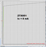
Maybe it will be useful to invest extra effort on estimating the PSRR of the very first stage, since any PSU noise that finds its way onto the first stage's output, is subsequently amplified by the rest of the preamp circuitry. Thus I imagine it would help to know the Early voltage of the ZTX851 "Q8" in the first stage power supply circuit. The small signal collector-to-emitter resistance of Q8, denoted r_ce, is proportional to Early voltage, and r_ce is the main pathway for power supply noise to corrupt the ultra sensitive DC potential at the top of R1. So we want enormous r_ce to achieve a very high PSRR. Bigger Early voltage means bigger PSRR in the first stage's dedicated supply filter circuit.
The SPICE model for ZTX851 on Diodes Inc's website says the Early voltage is 158V. However, I measured it myself {plot below} and found an Early voltage of 267V. My eyeball tells me that at Vce of 6.0V, Ice=8.2mA ; and at Vce of 16.0V, Ice=8.5mA . Punching it up on a calculator, that gives Vearly = 267 volts. You can spend some time wondering whether I got a rare and lucky unit, or whether Diodes Inc conservatively underestimates Vearly for their released-to-customers SPICE models, or whether the manufacturing process changed for the better (my unit fabbed after SPICE model unit), or whether the manufacturing process changed for the worse (my unit got the old process, SPICE model unit got the new), or ...
Have fun and good luck!
- The circuit schematic of Pearl 3 ; attached to post #1 in this thread
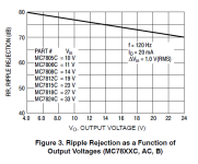
- The ripple rejection plots of the IC voltage regulators ("U3" + "U4") used on the Pearl 3 PCB {example attached}
- The PSRR plots of the IC opamps used in Pearl 3 ("U1A" + "U1B")
- Your own personal estimate of the aggregate transconductance gm of the first stage (Q1-Q4 with R4-R7)
- The gain of the first stage (your_gm * R1)
- Your own personal estimate of the PSRR of the first stage's power supply filter circuit (R19-R21, C7, Q8, C6)
Maybe it will be useful to invest extra effort on estimating the PSRR of the very first stage, since any PSU noise that finds its way onto the first stage's output, is subsequently amplified by the rest of the preamp circuitry. Thus I imagine it would help to know the Early voltage of the ZTX851 "Q8" in the first stage power supply circuit. The small signal collector-to-emitter resistance of Q8, denoted r_ce, is proportional to Early voltage, and r_ce is the main pathway for power supply noise to corrupt the ultra sensitive DC potential at the top of R1. So we want enormous r_ce to achieve a very high PSRR. Bigger Early voltage means bigger PSRR in the first stage's dedicated supply filter circuit.
The SPICE model for ZTX851 on Diodes Inc's website says the Early voltage is 158V. However, I measured it myself {plot below} and found an Early voltage of 267V. My eyeball tells me that at Vce of 6.0V, Ice=8.2mA ; and at Vce of 16.0V, Ice=8.5mA . Punching it up on a calculator, that gives Vearly = 267 volts. You can spend some time wondering whether I got a rare and lucky unit, or whether Diodes Inc conservatively underestimates Vearly for their released-to-customers SPICE models, or whether the manufacturing process changed for the better (my unit fabbed after SPICE model unit), or whether the manufacturing process changed for the worse (my unit got the old process, SPICE model unit got the new), or ...
Have fun and good luck!
Attachments

Last edited:
Hello @jackinnj ,Id 5.3mA from the simulation. (J5 in the attached file)
Will you post your LTspice library?
Thanks DT
@DT
The models are from Bob Cordell's website. The BJT's like ZTX are on Diodes Inc. website. LTwiki is also helpful. PM Me for anything you need.
I "misconnected" the inverting input of U1a to the emitter of Q5 in the LTSpice file, it should be connected to the collector.
To create the data in the charts below, I used Q5 to drive a 1.5k resistor rather than the 4x LSK170s. The Pearl 2 uses 3.2mF caps whereas the Pearl 3 uses 220uF. I repeated the trials many times and would certainly appreciate anyone else repeating.
In any event, the Pearl 2 is my go-to RIAA pre-pre, and I look forward to using the Pearl 3!
Attachments

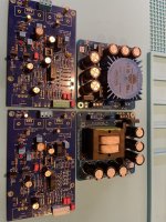
The caps and balanced driver chips arrived, and now there installed.
I checked my stash and see 5532 and LME49720. Let’s start with 49720’s
My heatsinks arrive Monday.
Everything else is ready to go.
I checked my stash and see 5532 and LME49720. Let’s start with 49720’s
My heatsinks arrive Monday.
Everything else is ready to go.
Attachments

Last edited:
Attaching balanced outputs to the test fixture.


Inclusion of the first stage in feedback loop drastically improved its PSRR. The simple topology of the first stage is otherwise pretty open to disturbance from power supply. Opamps are inherently much more robust, no issue there anyway.Edit: everybody seems to 'know' that the '3 has a high PSRR but nobody is able to come up with some numbers or measurements.
So, how do you know then??
Jan
I am not intending to do that Mark.Jan, if you want to estimate Pearl 3's PSRR yourself, using pencil and paper calculations, I recommend you start with a few pieces of data:
I would expect that those who wax lyrical about it would be able to tell me why they do; those who make the claim should be able to give the proof.
As far as I can see, jackinnj is the only one who actually verified it.
Jan
- Home
- Amplifiers
- Pass Labs
- Pearl 3 Burning Amp 2023