Not sure if PCB+semiconductors will be an option. Probably. There will be kits of PCB+ everything on the board.
It is doubtful that bare PCB will be offered.
It is doubtful that bare PCB will be offered.

He answered you. In his charming zenglish manner 🙂
50k will work just fine, and if your DAC recommends it, by all means use it, no issues at all. 25k, 20k, 10k will also all work beautifully.
From the DRV135 data sheet -
• Low Distortion: 0.0005% at f = 1 kHz
• Wide Output Swing: 17Vrms into 600 Ω
• High Capacitive Load Drive
It's a balanced line driver, literally intended to run 30-50m of balanced cable all across studios and patch panels. 17V into 600ohms is a lot of current and voltage both.
ZM was trying to mention that the Pearl 3 output stage itself could run headphones. (maybe not ideally, but would still work...) The DRV135 could as well.
Yes, of course. My bench pre is a Waynes BA2018 and it works beautifully well!
50k will work just fine, and if your DAC recommends it, by all means use it, no issues at all. 25k, 20k, 10k will also all work beautifully.
From the DRV135 data sheet -
• Low Distortion: 0.0005% at f = 1 kHz
• Wide Output Swing: 17Vrms into 600 Ω
• High Capacitive Load Drive
It's a balanced line driver, literally intended to run 30-50m of balanced cable all across studios and patch panels. 17V into 600ohms is a lot of current and voltage both.
ZM was trying to mention that the Pearl 3 output stage itself could run headphones. (maybe not ideally, but would still work...) The DRV135 could as well.
To feed Wayne's line stage perhaps?
Yes, of course. My bench pre is a Waynes BA2018 and it works beautifully well!
Last edited:
Balanced?My bench pre is a Waynes BA2018 and it works beautifully well!
No. mine is SE. Of course it would work perfectly if a balanced BA2018
Main system has an XP-12, I'm running it to the balanced inputs there.
Main system has an XP-12, I'm running it to the balanced inputs there.
Weren‘t you guys philosophing about modding a ortofon to center-tap its motor?
🏴☠️
Just read about pro-ject doing precisely this, FWIW…
https://www.project-audio.com/en/turntable-must-have-accessories-copy/
🏴☠️
Just read about pro-ject doing precisely this, FWIW…
https://www.project-audio.com/en/turntable-must-have-accessories-copy/
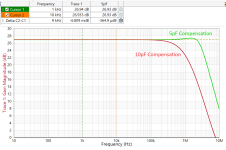
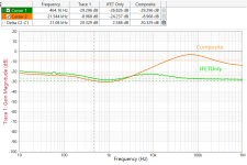
I should be outside raking leaves, but... I show the PSRR for the JFET only, and the composite amplifier. Gain is 27dB.
Also shown is the effect of the compensation capacitor on U1a. In this case LM4562
Also shown is the effect of the compensation capacitor on U1a. In this case LM4562
Attachments
Last edited:
OPA604 can handle +/-24V.24v regulators were changed to 15 to accommodate the opamps. (Although it may be a bit noisy if you burnt up them with +/-24v!)
Jack, that zero line does that signify 'no ripple/noise breakthrough' being infinite PSRR?I should be outside raking leaves, but... I show the PSRR for the JFET only, and the composite amplifier. Gain is 27dB.
Also shown is the effect of the compensation capacitor on U1a. In this case LM4562
Jan
The Zero Line represents the signal impinged upon the positive rail transmitted in its entirety. Adjust for 27dB of gain and PSRR is ~57dB @1kHz.
I used 2SK170GR running @2.6mA, 26mS
I used 2SK170GR running @2.6mA, 26mS
Thanks jackinnj,@DT
The models are from Bob Cordell's website. The BJT's like ZTX are on Diodes Inc. website. LTwiki is also helpful. PM Me for anything you need.
I "misconnected" the inverting input of U1a to the emitter of Q5 in the LTSpice file, it should be connected to the collector.
To create the data in the charts below, I used Q5 to drive a 1.5k resistor rather than the 4x LSK170s. The Pearl 2 uses 3.2mF caps whereas the Pearl 3 uses 220uF. I repeated the trials many times and would certainly appreciate anyone else repeating.
In any event, the Pearl 2 is my go-to RIAA pre-pre, and I look forward to using the Pearl 3!
I am going to solder and measure first, simulate second.
The weather is still clear and bright at the beach, which is competing for my fun time as well.
I am looking at your PSRR plots and thinking that you are testing the input stage of the Pearl 3 pre without the 7815 regulator between your bench power supply and the input stage capacitance multiplier.
The reduced PSRR of the Pearl 3 is eye opening.
Also thinking that CH 2 of the Bode 100 samples the input stage voltage at the collector of the bottom ZTX851.
Please correct me where/if I go wrong.
https://www.omicron-lab.com/fileadmin/assets/Bode_100/ApplicationNotes/PSRR/App_Note_PSRR_2_0.pdf
I am planning to assemble a couple of breadboards; one with 7815 and 7915 regulators on board, the other with the P3 input stage to drive a 1.5k resistor in place of the JFETS. Then measure with belt (regulator), suspenders (capacitance multiplier) and both together.
Thanks DT
Hi Jim, out of curiosity what cartridge are you using on the Technics? Looks to be an Ortofon, but which model? ThxAdventures from the bench. This sounds fantastic, even in the not-even-close-to-optimal lab “chassis” made from some random panels in my closet.
View attachment 1227856
Assume power supply voltage noise at the output of the LM7815, is RAILNOISE volts (over a 44 kHz bandwidth)
Assume Pearl 3's PSRR is PSRR3 volts per volt: (noise on Pearl 3's output) / (noise on the 7815 output)
Assume Pearl 3's voltage gain for moving coil setting, is PREAMPGAIN volts per volt
Assume the moving coil cartridge produces INPUTVOLTS of signal at the Pearl3 input
OK that's all the assumptions we need. Now we calculate.
The noise at Pearl3's output is therefore OUTPUTNOISE = (RAILNOISE * PSRR3) {equation 1}
The equivalent input voltage noise, which would produce OUTPUTNOISE at the output, is therefore INPUTEQUIVNOISE = (OUTPUTNOISE / PREAMPGAIN) . {equation 2}
The signal to noise ratio at the input is therefore SNRINPUT = (INPUTVOLTS / INPUTEQUIVNOISE) {equation 3}
Now let's plug in some representative values:
Tapping away on the calculator, we find
How does this happen? Plug equation 1 into equation 2 and you find that
So I don't think you need to worry too much about Pearl 3's PSRR.
Supply noise is negligible; it is completely dominated ("swamped") by cartridge noise.
Supply noise is negligible; it is completely dominated ("swamped") by cartridge noise.
Supply noise is negligible; it is completely dominated ("swamped") by cartridge noise.
Assume Pearl 3's PSRR is PSRR3 volts per volt: (noise on Pearl 3's output) / (noise on the 7815 output)
Assume Pearl 3's voltage gain for moving coil setting, is PREAMPGAIN volts per volt
Assume the moving coil cartridge produces INPUTVOLTS of signal at the Pearl3 input
OK that's all the assumptions we need. Now we calculate.
The noise at Pearl3's output is therefore OUTPUTNOISE = (RAILNOISE * PSRR3) {equation 1}
The equivalent input voltage noise, which would produce OUTPUTNOISE at the output, is therefore INPUTEQUIVNOISE = (OUTPUTNOISE / PREAMPGAIN) . {equation 2}
The signal to noise ratio at the input is therefore SNRINPUT = (INPUTVOLTS / INPUTEQUIVNOISE) {equation 3}
Now let's plug in some representative values:
- RAILNOISE = 250 microvolts over a 44 kHz bandwidth; from TI LM7915 datasheet. (The worst noise spec of all 7915 datasbeets)
- PSRR3 = 1.41E-3 (assumes jackinnj's -57 dB estimate is exactly correct)
- PREAMPGAIN = 6.31E+3 (assumes Wayne's +76 dB estimate (for moving coil) is exactly correct)
- INPUTVOLTS = 1.2E-4 (i.e. 0.12 millivolts) for moving coil
Tapping away on the calculator, we find
- OUTPUTNOISE = 3.53E-8 volts over a 44 kHz bandwidth
- INPUTEQUIVNOISE = 5.60E-11 volts over a 44 kHz bandwidth; that's 56 picovolts
- SNRINPUT = 2.14E+6 (which is 126 dB when you ONLY consider supply noise. Wow! Cowabunga!)
How does this happen? Plug equation 1 into equation 2 and you find that
- INPUTEQUIVNOISE = ((RAILNOISE * PSRR3) / PREAMPGAIN))
So I don't think you need to worry too much about Pearl 3's PSRR.
Supply noise is negligible; it is completely dominated ("swamped") by cartridge noise.
Supply noise is negligible; it is completely dominated ("swamped") by cartridge noise.
Supply noise is negligible; it is completely dominated ("swamped") by cartridge noise.
Last edited:
Hi Jim, out of curiosity what cartridge are you using on the Technics? Looks to be an Ortofon, but which model? Thx
In that photo the -1200 has Ortofon OM10 mounted.
Main system currently has AT-OC9 Moving Coil, which is working wonderfully at this very moment with Pearl 3. Also have been playing with the new AT-VM95SH which is a fantastic cartridge and punches so far above it’s price class it’s crazy.
Got the little guys soldered. Helpful tip from @6L6 was to check the voltage drop from gate to source and gate to drain of each little guy, to make sure they got soldered correctly & not cooked. A good exercise, I got 0.680V gate to drain, 0.691V gate to source across all 4 on 1 board; 0.679V and 0.690V across the other 4 on the other board.

I can’t take credit for that as I was chatting about testing soldering continuity a week ago with @thomasnadeau , and he remembered that Jfet will measure as diodes from Source to Gate and from Drain to Gate…
So on this PCB you can set your DMM to diode test, place the red probe on the through-hole pad for gate, and black probe on through hole pad for Drain, and then black to the pad for Source. In each instance if it shows about 0.7v from D-G and then S-G, you’ve verified that 1) the SMD have continuity to the pcb, and 2) you don’t have blown jfet. Cool!
This will be shown clearly in the guide.
- Home
- Amplifiers
- Pass Labs
- Pearl 3 Burning Amp 2023