

Still loving my Pearl 2, and my B1, for that matter, but this looks so good, and it’s been too long since I built anything. So please count me in for a chassis.
Couldn't wait... lured the 13-year-old for a test run with a little TS, she was game (apparently Swift cares about vinyl—it IS a fact that the record sounds 100% better to us than hi-res digital). Haha.
We thought the sound was excellent at first firing! BUT...
During the fact checking I noticed that the right channel was wasn't right—we could hear faint playback—but not like the left channel. Quick RCA swaps confirmed some issue with the right board. The music sounded SO GOOD from just one speaker—we didn't catch it at first.
I did a little chop-sticking—I'd already tested the jfets per another post in this thread—Leave it to our collective special someone (@6L6) to request some clear images and in perfect form he saw my error in maybe 5 seconds (okay, 3 seconds). 10K instead of 10R for source resistors in the right board! PERFECT!
Quick from-the-top-swap and all is well. FANTASTIC. Great bass, open highs—no complaint's. Will do some critical listening tomorrow.
Thanks Wayne! Thanks Jim! More later...
(Good competition there in the pic, Salas Ultra, WP Phono)
Nice that you can share your listening with your boy, and glad you found the problem and can enjoy music 100%... can't wait to read your findings on these great phono pres - well done!
Thanks for sharing all this and have fun both of you during the listening sessions
Claude
Thanks for sharing all this and have fun both of you during the listening sessions
Claude
Hello,
Is it the banana or the banana peel?
With the P3 enclosure or the P3 power supply enclosure which is it that you keep away from the other?
If it is the P3 enclosure that is sensitive to EMR radiation you may also want to keep it away from the 2118 line stage as well as any other power supply.
Any P3 FFT plots / noise floor plots some one wants to share?
Thanks DT
Last edited:
beautiful
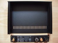
Super! Definitely interested 😃The chassis set will be available, and soon. Not sure if directly from Gianluca only or stocked in the diyAudio store as well, but here's the overall look - (please note these are the prototypes, and these same chassis will be in the build guide. The biggest difference is production will have steel top and bottom panels, as it is better shielding.)
If you have interest in this chassis set, please say so in this thread.
Cost is not finalized and still to be determined, but somewhere in the vicinity of 200EUR, most likely less. Of course this does not include the jacks, plugs, and such.
View attachment 1238779
View attachment 1238780
View attachment 1238782
View attachment 1238783
No panzerholz. Very hard to get here, probably minimums.. and I’m not sure the difference would be audible.. slate would be easier. That plinth and the other in process for deck two are baltic birch multiply stacks, what’s sometimes called Russian ply, comes is 5x5 sheets. Very dense, no voids. I also put 25lbs of lead (flattened old telephone bundle casings) in the bottom. The second deck plinth may have a bonded aluminum sheet layer… not sure yet.@pfarrell
Nice deck. Panserholtz(sp?) plinth?
I neglected to express my appreciation to @wayne for his wonderful design, and for making this project available to us all. We're always so fortunate to have skilled professionals creating cool projects for us to build and enjoy. Also, thank you Wayne, for sending me the single board to make up my pair, and for continuing to provide input as this project develops.
What is particularly interesting about this phono preamp is the flexibility - the ability to select among a wide variety of active devices. It's also a really, really nice sounding phono preamp. I've got maybe 8-9 different phono preamps, a couple of head amps, several SUTs, and all have their strengths and some have weaknesses. After using this in its temporary chassis for 5 hours yesterday, even with a non-optimal power supply, I can say it sounds as good as my best phono preamps.
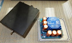
The only modification I made was to install a trimmer in place of R27, since I couldn't get the bias voltage to be identical between both boards with fixed resistors on hand. There is no point in taking any performance measurements until it is installed in its dedicated enclosure, but I will do so if only to get more practice with measurements!
The power supply board is now complete except for adding the snubber resistor as measured with Quasimodo, moving the blue power on LED to the front of the enclosure and completing assembly.
What is particularly interesting about this phono preamp is the flexibility - the ability to select among a wide variety of active devices. It's also a really, really nice sounding phono preamp. I've got maybe 8-9 different phono preamps, a couple of head amps, several SUTs, and all have their strengths and some have weaknesses. After using this in its temporary chassis for 5 hours yesterday, even with a non-optimal power supply, I can say it sounds as good as my best phono preamps.
The only modification I made was to install a trimmer in place of R27, since I couldn't get the bias voltage to be identical between both boards with fixed resistors on hand. There is no point in taking any performance measurements until it is installed in its dedicated enclosure, but I will do so if only to get more practice with measurements!
The power supply board is now complete except for adding the snubber resistor as measured with Quasimodo, moving the blue power on LED to the front of the enclosure and completing assembly.
Attachments
I don't think it's important to match the JFET CCS currents (Q9 / R27) and seemingly, neither does Wayne C. However if you wish to gild the lily, it's your set of boards and you can build them however you want. Nobody else gets a vote.
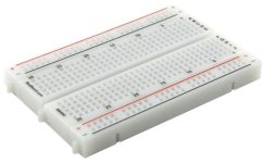
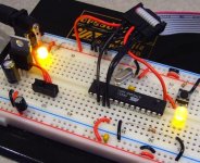
I guess you could use a solderless breadboard and some pluggy wires to make a little homebrew jig. It measures the constant current of a J112 JFET and a 220 ohm source resistor (same CCS circuit as Q9 and R27). Then grab your stash of J112s and measure the CCS value of each one, in your jig. Writing down the measured values of course. When all done, choose two J112s that give the most tightly matched constant current sources. Use those two J112s in your Pearl 3.
_
Attachments
Last edited:
Thank you, Mark - that is actually what I had intended to do, after I order some more J112s. Of course, I have a stash of 50 J113s, but any J112s? Ha.🙄
- Home
- Amplifiers
- Pass Labs
- Pearl 3 Burning Amp 2023