Correcting my previous post about the change in value of R27 - meant to write 47R, NOT 470R.
Only had 49.9R in 1%, so used those, now bias is perfect.
I do not like captive power cables in both boxes, nor do I like cables detachable from both boxes, since over time it gets lost. Not a big problem if XLR cables are used, I suppose. For the most part, I prefer captive cables on the PS, detachable from the main box, ala my Threshold gear and my own variety of builds.
One exception is my Counterpoint SA-3000, which had a very inconvenient captive cable. It was much easier to put a female jack on the PS box and keep the cable captive on the preamp box due to the numerous conductors.
Beautiful, Jim! I think your design of the chassis panels is perfect for this.
@rhthatcher did all the work and made them real, my part was just a sketch or two. I think they look outstanding!


Great enclosure, would certainly to have the front and back panels. Great work!
SB
SB
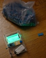
I received my bag of 1000 pcs KEMET 100nF (+- 5% tolerance) and was looking forward to a relaxing evening with screening / measuring a batch of caps for P3 that was within -+1%.
The problem is that they seems to be manufactured too accurate as first 10 measured were all in between 99.5 - 100.5 nF.
So what to do now with rest of caps?
Ok....I could continue and get some within 99.8 - 100.2 nF.
When I do repeated readings (which I do) it can vary a little.
I think with this equipment it will make no sense to try to measure more accurate.
I have a prof. unit with Kelvin probes and I think I will do some control measurements. Using this equipment I can also measure using different frequencies (e.g. 100, 1000, 10000 Hz). But probably the Kelvin probes are too "clumsy" for such small caps (wires are short).
I wonder if the pictured "tool" is what 6L6 call a Mega328 ?
Attachments
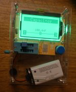
The tester showed only shows capacitance. I have another of the cheap gadgets with also shows ESR, a loss factor etc.
The HIOKI 3522 LCR tester I have also shows a lot of parameters (vintage tester I got from a friend which could find no use for it).
Some of my DMM's also has a "Capacitance" setting.
The pictured tester is very easy and fast to use. The 5mm pitch fits perfect in the test socket.
The HIOKI 3522 LCR tester I have also shows a lot of parameters (vintage tester I got from a friend which could find no use for it).
Some of my DMM's also has a "Capacitance" setting.
The pictured tester is very easy and fast to use. The 5mm pitch fits perfect in the test socket.

Yes, the HIOKI has only 4 x BNC input and the only probe I have for it is the Kelvin probe.
Probably possible to make some more practical interface for these small components.
As the cheap tester shows values just below and just above 100 nF I suspect it to be accurate.
For resistors I may use the Kelvin approach.
Probably possible to make some more practical interface for these small components.
As the cheap tester shows values just below and just above 100 nF I suspect it to be accurate.
For resistors I may use the Kelvin approach.
Hello,
You know it doesn't matter all that much which tool that you use to measure, as using the same tool to measure matching parts for both Left and Right channels, you want both channels to sound the same.
I use a Rhode & Schwarz RCL a Bode 100 VNA or a Keysight B2912A with and without Kelvin leads. It does not matter, just do both sides the same.
My Fluke Digitial meter does just fine.
Thanks DT
May I know where I can purchase the PCBA...It's so intoxicating looking at those fantastic DIY pictures of Pearl3..😉
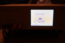
I performed a control measurement using the HIOKI using the famous Kelvin probes.
It showed 99.5 nF where the tester used above showed values from 99.2 - 99.6 nF (this tester measures continuously).
A DMM I have showed just 98 nF on all the caps I have tested so far.
A MK-168 transistor tester showed 97.x nF (this tester also a cheap gadget).
I will use the first one I used with easy test socket and take some reading and use an average.
It is nice to know the exact nominel value for riaa accuracy and also that L / R ch have same values.
Attachments

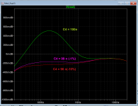
How to interpret this?
The green curve is with C4 = 100 nF and is considered the "correct" curve?
The change in curve form is huge from 100 nF to 99 nF and not so much from 99 nF to 90 nF?
The green curve is with C4 = 100 nF and is considered the "correct" curve?
The change in curve form is huge from 100 nF to 99 nF and not so much from 99 nF to 90 nF?
Something appears to wrong though, the ESR and ESL should be nulled out in calibration.I performed a control measurement using the HIOKI using the famous Kelvin probes.
I can try again by doing a calibration.
The instrument has a calibration where the probes are shorted. I did not do this for the quick measurement.
It also has an open circuit calibration which takes "forever" to finish.
The instrument has a calibration where the probes are shorted. I did not do this for the quick measurement.
It also has an open circuit calibration which takes "forever" to finish.
Smd version done 🙂 40x65mm. Regulators onboard lt3094 and lt3045, with option to solder in 78xx and 79xx. And an option for non smd output pair for testing. Personal use only.

We're getting a little bit into the weeds of impedance testing, you might want to fashion an "open, short, load" calibration fixture with a precision (0.1%) 100R 1210 SMD resistor. We can discuss impedance testing in a separate thread. (I dislike thread-jacking)
Yes, I did a short circuit calibration but it did not change much. The test freq. above was 1 kHz.
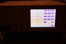
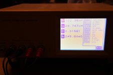
Just to finish this in this thread. Couple of images added (calibration short result, 400 Hz result (Ls = 1.6H, 100 kHz result, Ls = 25uH).
As can be seen the Ls (series inductance) varies a lot with frequency. So it is good I know it is a small cap.
Probably if I read (and understand) the documentation of the unit I will have the answer.
In highschool this was done with some ref. caps or resistors and a bridge setup and a meter to show when in "balance".
Wheatstone bridge I remember. Don't know how these modern instruments works inside in detail (even that "this" instrument is vintage).
Interesting how the above smd version P3 performs.
My 1000 pcs. 100 nF caps are not smd!
Attachments
- Home
- Amplifiers
- Pass Labs
- Pearl 3 Burning Amp 2023