Yes but what's the point except for proving a point? Isn't 3 or 4pF like two short insulated wires taped together..? Yes of course I'll try it. Since you didn't comment I'm assuming C0G ceramic disk is OK.
I'd just like to know how high and low you can go before things go wrong, so you can pick values that are nowhere near the edges of that range. It would be a pity if a slight temperature change or a bit of long-term drift would cause the problem to come back. C0G is fine.
Attached is a RIAA preamp design from a design article featuring a number of possibles for MC and MM carts written by Aussi Rod Elliot of "ESP". This one he explains has a special feature not always seen and that is the inclusion of some RF immunity. He points to the grayed-out 220pF as a sometimes-used cart loading cap and that it's a bad idea so it's not there for RF. R3 and C3 seem to be the active players to me. What's the opinion on this R/C configuration method of preventing run-away excitation?
Won't C3 seriously degrade available gain for NFB at higher frequencies?
It reduces loop gain at higher frequencies and causes an extra phase shift in the loop that eats up a part of the phase margin. The trick is to find some compromise value that filters RF enough without changing the amp into an oscillator.
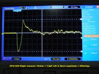
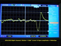
For this 3rd R/C damping trial the combo was 1KΩ + 3.8pF (approx.) placed across the Right channel’s RCA connector’s inside terminals. The 3.8pF was fashioned from 2x 6.8pF C0G ceramic disks in series. TT cables were plugged in normally; scope shots were taken off of a RCA male plugged to the Right output and the Left output cable remained connected to the system preamp for the PE reference. This was the pre-test exercising just the TT’s mute switch (aka Test #2) to determine if a listening test was warranted. This damping combo failed due the level of the Lift and Lower output disturbance.
Of possible note is that the Lift&Short transient has a clean front-end followed by a LF trail of trash. The Lower&Open transient is led by LF trash with a clean back-end.
Of possible note is that the Lift&Short transient has a clean front-end followed by a LF trail of trash. The Lower&Open transient is led by LF trash with a clean back-end.
Attachments
(Almost) Purely going for my gut feeling here, but IMHO you should go in the direction of less resistance, more capacitance. Not in the other direction like you're doing right now.
I could explain this but I fear I might have my gut-feeling-math all wrong. 😉
I could explain this but I fear I might have my gut-feeling-math all wrong. 😉
Seems so to me as well but I was just doing what Marcel suggested I try next. He's trying to find the invisible wall I think.
Right now we have:
220R/15pf = Good
470R/~7pF = Better
1K/3.8pF = Bad
Right now we have:
220R/15pf = Good
470R/~7pF = Better
1K/3.8pF = Bad
Last edited:
OK, so that's too small. Could you try 33 pF, 100 ohm?
If that works, then I would suggest using 15 pF, 220 ohm as the solution, because it is then at least a factor of two away from any invisible walls/edges of cliffs and its capacitance is acceptable to you. It's a pity that the click with 15 pF, 220 ohm is somewhat worse than with 7 pF, 470 ohm for unclear reasons.
If that works, then I would suggest using 15 pF, 220 ohm as the solution, because it is then at least a factor of two away from any invisible walls/edges of cliffs and its capacitance is acceptable to you. It's a pity that the click with 15 pF, 220 ohm is somewhat worse than with 7 pF, 470 ohm for unclear reasons.
(Almost) Purely going for my gut feeling here, but IMHO you should go in the direction of less resistance, more capacitance. Not in the other direction like you're doing right now.
I could explain this but I fear I might have my gut-feeling-math all wrong. 😉
It's also what I expected, but for some unclear reason JRA hears and measures bigger disturbances with 15 pF, 220 ohm than with 7 pF, 470 ohm.
Might have to do something with the disturbances added by the measurement setup (lossy coax cable from the scope probe etc?)
EDIT: to rule out some of these smallish disturbances I would go to at least double capacitance/half resistance to see if it really gets worse in that direction...
EDIT: to rule out some of these smallish disturbances I would go to at least double capacitance/half resistance to see if it really gets worse in that direction...
Last edited:
Don't think so. The scope is on the 1656's output albeit after a post roll-off R-C filter. That's there b/c of the zero formed by the non-inverting, unity gain limitation. RIAA says hi-freq roll-off goes "forever". Anyway, the output impedance is 330 ohms so no worries.
Edit: OK I'll cook-up a brand new combo.
Edit: OK I'll cook-up a brand new combo.
Last edited:
You never tried to shorten C4 which could have revealed something.
With Marcel’s plausible theory of oscillating at a very high frequency, C4 at this frequency has a very high impedance acting almost as a coil instead of a cap, making overall stability likely inferior as with C4 shorted.
But as an alternative instead of shortening C4 as a test, you could place a 1nF cap in parallel to C4, giving the combo a much lower HF impedance.
Hans
A small capacitor like a 1 nF might create more problems. Since the ESL of an electrolytic could be 20 nH while the ESR is likely less than 1 ohm you could be setting up a high Q parallel resonant tank, which would mess up your phase margins.
This has bugged me for a while: since ceramic capacitor ESLs are more or less the same for a given size of capacitor independent of value, why not use microfarad scale bypass caps for electrolytics, for example 2.2 uF ceramic in parallel with 100 uF electrolytic? That way the Q of the created tank would be lower than it would be for smaller capacitor values. The cost difference isn't terribly great: 2.2 uF parts are maybe twice 0.22 uF, and perhaps thrice 0.022 uF, at about $0.75 vs $0.40 vs $0.25. Given electros are more than that anyway it's kind of a no-brainer.
Don't think so. The scope is on the 1656's output albeit after a post roll-off R-C filter.
Yep, thinking about it you're right, you're measuring at a low impedance node - at the output of the opamp and not at the input.
This has bugged me for a while: since ceramic capacitor ESLs are more or less the same for a given size of capacitor independent of value, why not use microfarad scale bypass caps for electrolytics, for example 2.2 uF ceramic in parallel with 100 uF electrolytic? That way the Q of the created tank would be lower than it would be for smaller capacitor values. The cost difference isn't terribly great: 2.2 uF parts are maybe twice 0.22 uF, and perhaps thrice 0.022 uF, at about $0.75 vs $0.40 vs $0.25. Given electros are more than that anyway it's kind of a no-brainer.
The bigger values are usually class 2 ceramic capacitors, which are terribly non-linear. Whether that matters depends on the application. In this case capacitor non-linearity will cause distortion, but the signal voltage is very small, so it won't be much distortion. Then again, you don't need much to exceed the OPA1656's ultralow distortion levels.
I was thinking more of power supply caps not far from the opamp pins. Ceramics in the signal path? Apart from NP0, ew.
The point wrt resonant tanks still holds. I took off on a tangent wrt C4 in the schematic, which probably led to some confusion about whether the ceramic bypass was intended for that particular application. Mea culpa.
Speaking of which, I wonder whether the ESL of C4 would be biting into the phase margin since it would increase loop gain at high frequencies. Nichicon MUSE have something like ~100 nH ESL.
That's a lot. The ESL causes a left-half-plane zero in the loop gain, so if it does anything, it should increase the phase margin. Probably not by much, though, as the feedback capacitors are essentially short circuits at the frequency where C4's ESL kicks in.
In this very case, writing and thinking what effect C4 might have takes many minutes, while trying a shortcut and/or a par cap less then a minute.
Like with the damping, only taking the practical road and trying several combinations will lead to optimal results.
Hans
Like with the damping, only taking the practical road and trying several combinations will lead to optimal results.
Hans
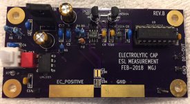
Couple years ago I built a gizmo that measures electrolytic capacitor ESL. It creates a resonant circuit between the inductance of the big eCap, and an external discrete ceramic C (in the super low inductance 0612 SMD package (reverse geometry)). Resonant frequency was around 10 MHz, well above the SRF of the eCap. The gizmo worked reasonably well, but then I gave myself permission to buy an ET1092A L/C/R/Z meter which worked even better.
link: Measuring the "ESL" inductance of electrolytic caps (at 10 MHz!)
_
link: Measuring the "ESL" inductance of electrolytic caps (at 10 MHz!)
_
Attachments
Last edited:
That's a lot. The ESL causes a left-half-plane zero in the loop gain, so if it does anything, it should increase the phase margin. Probably not by much, though, as the feedback capacitors are essentially short circuits at the frequency where C4's ESL kicks in.
You are of course correct. That'll teach me to post on no sleep 😛
In this very case, writing and thinking what effect C4 might have takes many minutes, while trying a shortcut and/or a par cap less then a minute.
Like with the damping, only taking the practical road and trying several combinations will lead to optimal results.
Hans
Would a Wima 0.1uF MKP10 across C4 show any effect or too small? Or I have 2.2, 3.3 and maybe larger in X7R ceramic. What you say Hans?
PS.
Disturbing news from yesterday's playing around is that the Right and Left halves of the DPST mute slide switch have different mechanical personalities in that they excite whatever it is about the 1656 differently. That new fact has skewed previous results. The Right channel is the more aggressive with a single pair of sharp + and - spikes like one sine wave cycle and that's pretty much it. The Left channel achieves lesser max amplitude but is a trail of multi-frequency gibberish.
Thus, the 2nd Damper R/C trial left the successful 1st trial 220F/15pF combo in-place on the (yet to be known) nastier Right channel input as a reference; removed the 220R/15pF from the Left and replaced it with the 2nd 470R/6.7pf combo. That 2nd combo performed audibly better b/c it had less to do...? I think that's why you guys felt the results conflicted with the math.
When I swapped TT input cables the Left channel winner of the 2nd trial the 470R/7pF now did poorly with the Right channel input challenge. If apples had been to apples (i.e. both TT channels = same personality) then the 220/15pf polystyrene would have not been bettered in the 2nd trial.
Therefore the new bottom line is, if they called a halt to these festivities and I had just these choices I'd go with the "Good enough" 220R/15pF combo; use the 1612A or 1656 if they sounded better than the current favorite and well-behaved OPA627. So that's today's blog.
So if I understand you correctly:
3.4 pF, 1 kohm does not work
6.8 pF, 470 ohm works
15 pF, 220 ohm works
Any perceived and measured differences between 6.8 pF, 470 ohm and 15 pF, 220 ohm were actually differences between left and right of your turntable.
Based on that information, I'd also choose 15 pF, 220 ohm.
3.4 pF, 1 kohm does not work
6.8 pF, 470 ohm works
15 pF, 220 ohm works
Any perceived and measured differences between 6.8 pF, 470 ohm and 15 pF, 220 ohm were actually differences between left and right of your turntable.
Based on that information, I'd also choose 15 pF, 220 ohm.
- Home
- Source & Line
- Analogue Source
- OPA1656 Phono Preamp: Split from OPA1656 thread