Well, never too old to learn, I never thought this was going to solve the problem.
Compliments to you Marcel.
Hans
Compliments to you Marcel.
Hans
I've had such weird problems due to oscillations (particularly in discrete circuits) that I immediately think of oscillations when something weird happens. 😉 Let's hope it keeps working, unlike the experiment with only a capacitor.
Last edited:
It likely would also have been solved with only a capacitor in a slightly higher value like 47 pF. The Audio Technica should be loaded with 200-300 pF as well. If all numbers are correct the situation is below 200 pF anyway.
BTW the use of tiny ferrite beads over the input wiring can be a good way to filter RF. Or to prevent it.
BTW the use of tiny ferrite beads over the input wiring can be a good way to filter RF. Or to prevent it.
Last edited:
According to post #590, the wiring alone is 195 pF (with a remarkably large part inside the turntable) and JRA's target is 200 pF total. I don't think there is a chance to meet that target, but if it can be made reliably stable with 15 pF and 220 ohm, at least it's close.
All good but what I meant that the result of 47 pF had also solved the issue not depending where one is coming from. I think it is not OK to skip any capacitance at the input (as in the old situation) and to depend solely on the cabling for that with 144 pF mentioned for internal cabling which seems high. Even the addition of a very low value cap already made a change that turned out to be not 100% reliable....but AFAIK no larger values were tested. That is all, no arguing.
Last edited:
Yesterday’s recap:
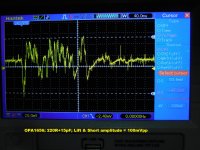
I applied one of Marcel’s R/C damper circuit combos at both L&R RIAA input connectors (i.e. before the board-mounted 47KΩ terminations) = 220R + 15pF polystyrene. That config caused the OPA1656 to become docile and passed all three muting switch tests. Same good behavior also from an OPA1612. A fully satisfying set of immediate results
Today I followed Marcel’s advice to try a combo of double the R and half of the C – looking for a limit or edge.
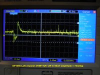
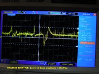
Today’s combo was 470R + ~7pF NP0 installed only in the Left channel.
The Right channel remained with yesterday’s 220R + 15pF damper combo.
First I must admit that yesterday’s comment re not even getting a scope trigger when doing the first two tests was wonderful but entirely bogus b/c today there was plenty of signal to trigger on.
I began with yesterday’s Right channel’s 220R + 15pF damper just to check my report and sanity but now found relatively docile but important Lift/Lower disturbances I’d missed. I also noted that my usual 8mS/div horizontal setting was not capturing the full length of the disturbance so I switched to 40mS/div.
Therefore, all the attached pics were done at 40mS/div so the sometimes rather long muting event is all there – up to many 10ths of a second.
I imagine some stuff is due to the slow-motion mating and/or un-mating of very old copper contacts in a slide switch and some elements are the 1656’s attempt to blast off. Just a WAG.
Bottom line today is that the new 470R+7pF damping shots show a better throttling of the 1656’s temperament in my build environment than the quite acceptable 220R+15pF damping combo used yesterday. The Left channel’s 470R+7pF damping effect is audibly quieter during muting. I can hear it. I don’t know why or how this R/C damping works with Marcel’s magic RxC of 3nS but it does.
>> Although not labelled, the first two scope shots are yesterday's Right channel.
I applied one of Marcel’s R/C damper circuit combos at both L&R RIAA input connectors (i.e. before the board-mounted 47KΩ terminations) = 220R + 15pF polystyrene. That config caused the OPA1656 to become docile and passed all three muting switch tests. Same good behavior also from an OPA1612. A fully satisfying set of immediate results
Today I followed Marcel’s advice to try a combo of double the R and half of the C – looking for a limit or edge.
Today’s combo was 470R + ~7pF NP0 installed only in the Left channel.
The Right channel remained with yesterday’s 220R + 15pF damper combo.
First I must admit that yesterday’s comment re not even getting a scope trigger when doing the first two tests was wonderful but entirely bogus b/c today there was plenty of signal to trigger on.
I began with yesterday’s Right channel’s 220R + 15pF damper just to check my report and sanity but now found relatively docile but important Lift/Lower disturbances I’d missed. I also noted that my usual 8mS/div horizontal setting was not capturing the full length of the disturbance so I switched to 40mS/div.
Therefore, all the attached pics were done at 40mS/div so the sometimes rather long muting event is all there – up to many 10ths of a second.
I imagine some stuff is due to the slow-motion mating and/or un-mating of very old copper contacts in a slide switch and some elements are the 1656’s attempt to blast off. Just a WAG.
Bottom line today is that the new 470R+7pF damping shots show a better throttling of the 1656’s temperament in my build environment than the quite acceptable 220R+15pF damping combo used yesterday. The Left channel’s 470R+7pF damping effect is audibly quieter during muting. I can hear it. I don’t know why or how this R/C damping works with Marcel’s magic RxC of 3nS but it does.
>> Although not labelled, the first two scope shots are yesterday's Right channel.
Attachments

It likely would also have been solved with only a capacitor in a slightly higher value like 47 pF. The Audio Technica should be loaded with 200-300 pF as well. If all numbers are correct the situation is below 200 pF anyway.
BTW the use of tiny ferrite beads over the input wiring can be a good way to filter RF. Or to prevent it.
How about snap-on cable ferrite cores? I have a collection of Fairite solid cores and snap-ons for 1/4" and 3/8" dia cables in multiple materials.
I would say that 470+7pF dampens less than 220+15pF, but your results are showing the opposite.
Could it be that you are still using the dual RCA input plug and that one input holds the damping network ?
Then your 470+7pF could easily be 470+12pF to 470+17pF because of the 5pF to 10pF added capacity of this dual RCA input plug.
If so, the time constant also changed quite a bit between the two damping versions possibly explaining the unexpected results ?
Hans
For these trials of the damping networks there are no external RCA gizmo connector adapters. The R and C are soldered to the RCA input connector tabs inside the box. TT input cables are connected straight-in like always. IOW, no changes other than an R and C in-series across the signal and shield input. I'm still clueless but the fix (both of them) is holding. I'm not having another brain fart...
You never tried to shorten C4 which could have revealed something.
With Marcel’s plausible theory of oscillating at a very high frequency, C4 at this frequency has a very high impedance acting almost as a coil instead of a cap, making overall stability likely inferior as with C4 shorted.
But as an alternative instead of shortening C4 as a test, you could place a 1nF cap in parallel to C4, giving the combo a much lower HF impedance.
Hans
I haven't got an explanation for this either. 7 pF will detune the resonance less than 15 pF, but during the earlier experiment without resistor, detuning it only helped (though not much).
The pragmatic thing to do would be to try both smaller and larger capacitances while keeping the RC product at about 3 ns. You will then see how high and how low you can go, and can then pick values somewhere in the middle.
You could also try other RC products than 3 ns as that 3 ns is just an order of magnitude estimate (and because I haven't accounted for the resonance detuning), but then you have a two-dimensional search space with lots of possible combinations.
Indeed, provided it's a small trimming pot and not a big pot with a large self-capacitance.
I'm a bit skeptical about the idea that shorting C4 will help to improve the stability, because as far as I know, the inductance of an electrolytic capacitor is of the order of 20 nH or so, depending on size. 20 nH at 50 MHz is only 2 pi ohm (or 2 pi j ohm).
Still, shorting C4 could make the measurements easier, because any offset due to oscillations will then probably remain at the output. You then only have to put the turntable in a state where the shorting switch is active and check the DC level at the amplifier output.
I haven't got an explanation for this either. 7 pF will detune the resonance less than 15 pF, but during the earlier experiment without resistor, detuning it only helped (though not much).
The pragmatic thing to do would be to try both smaller and larger capacitances while keeping the RC product at about 3 ns. You will then see how high and how low you can go, and can then pick values somewhere in the middle.
You could also try other RC products than 3 ns as that 3 ns is just an order of magnitude estimate (and because I haven't accounted for the resonance detuning), but then you have a two-dimensional search space with lots of possible combinations.
Marcel, you will have to put the above into regular electrical engineering terms. I am a retired EE but my career knowledge doesn't include the meanings of your 1st and 3rd paragraphs. Pick a different nS product..? Two-dimensional search space..? Decipher please. I like knowing why I'm trying something.🙂
And I don't have anything <6.8pF. The 7pF was just one on the high-side of the handful I had and about 1/2 of 15pF. Do you think C0G/NP0 ceramic disc vs. polystyrene film could be a player in the results?
Btw, I would have preferred that the 220R/15pF combo worked better. 7pF just seems like you know, too small, in the land of parasitics. But it went the other way. Standing at my equipment rack with the TT on top and flanked by the speakers, it's obvious that the left channel is quieter than the right - and the scope agrees. But, I'm still up for bracketing this thing. I'd like it if you guys approved of the final solution.
PS, FYI
I have three full-function preamps. Two are semi-legacy vacuum tube from the mid-90s and one is modern. This line-stage only Hegel is a fourth. All of the preamps with internal phono stages give some audible indication when the mute switch operates so it's always been there in minor form.
Last edited:
Attached is a RIAA preamp design from a design article featuring a number of possibles for MC and MM carts written by Aussi Rod Elliot of "ESP". This one he explains has a special feature not always seen and that is the inclusion of some RF immunity. He points to the grayed-out 220pF as a sometimes-used cart loading cap and that it's a bad idea so it's not there for RF. R3 and C3 seem to be the active players to me. What's the opinion on this R/C configuration method of preventing run-away excitation?
Attachments
Regarding the first paragraph: the inductance and capacitance of the cable together cause its resonances. It's similar to an LC parallel tank (but not exactly the same because the inductance and capacitance are distributed over the length of the line). When you connect a capacitor to the end, you increase the capacitance of the "tank" and reduce its resonance frequency. I have no idea if that should make it better or worse, but in your previous experiment with only a 15 pF capacitor, it made things better: from not working at all, it changed into sometimes working and sometimes not.
Third paragraph: I don't know if RC = 3 ns is optimal, it could be that a somewhat higher or lower value works better. The number of measurements may get rather large when you change both the capacitance and the time constant, though.
Third paragraph: I don't know if RC = 3 ns is optimal, it could be that a somewhat higher or lower value works better. The number of measurements may get rather large when you change both the capacitance and the time constant, though.
Yes but what's the point except for proving a point? Isn't 3 or 4pF like two short insulated wires taped together..? Yes of course I'll try it. Since you didn't comment I'm assuming C0G ceramic disk is OK.
He points to the grayed-out 220pF as a sometimes-used cart loading cap and that it's a bad idea so it's not there for RF. R3 and C3 seem to be the active players to me. What's the opinion on this R/C configuration method of preventing run-away excitation?
I think the idea is to minimize the loop area between the capacitor and the inputs of the op-amp. That makes sense when the RF is inside the enclosure of the amplifier, that is, when its enclosure doesn't shield RF well. Otherwise you might as well put a low-pass at the input (*). A complication is that the extra capacitor can affect the stability of the feedback loop.
(*): For a cartridge that can't handle much capacitance, Rod Elliot's method has the advantage that it adds almost nothing to the input capacitance at audio frequencies. For your circuit and turntable with the shorting switch, I don't know if it would solve or aggravate the oscillations.
Last edited:
- Home
- Source & Line
- Analogue Source
- OPA1656 Phono Preamp: Split from OPA1656 thread