Yes you understand perfectly. I'll reconstruct the two 220F/15pF poly's and check again for sanity.
So if I understand you correctly:
3.4 pF, 1 kohm does not work
6.8 pF, 470 ohm works
15 pF, 220 ohm works
Any perceived and measured differences between 6.8 pF, 470 ohm and 15 pF, 220 ohm were actually differences between left and right of your turntable.
Based on that information, I'd also choose 15 pF, 220 ohm.
Do you think it significantly matters whether the damper is just inside the metal shell on the RCA connector or down on the board // the 47K?
My favourite to start with would still be to shorten C4 because this reveals most of all. When nothing spectacular comes out in terms of better behaviour or strange DC jumps, remove the short circuit and leave C4 as it is now.Would a Wima 0.1uF MKP10 across C4 show any effect or too small? Or I have 2.2, 3.3 and maybe larger in X7R ceramic. What you say Hans?
The OPA627 is my all time favourite in this sort of applications, so I’m looking forward to hear your final judgement.Therefore the new bottom line is, if they called a halt to these festivities and I had just these choices I'd go with the "Good enough" 220R/15pF combo; use the 1612A or 1656 if they sounded better than the current favorite and well-behaved OPA627. So that's today's blog.
Hans
Probably not.
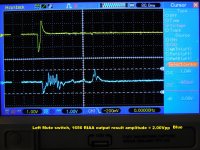
Here are the scope shots showing difference in raw output due to different mute switch personalities. This is all stock setup, no damping, TT straight in, scope probes on R&L 1656 RIAA EQ outputs. Same trace, diff is voltage cursors. Weird.
Attachments

My favourite to start with would still be to shorten C4 because this reveals most of all. When nothing spectacular comes out in terms of better behaviour or strange DC jumps, remove the short circuit and leave C4 as it is now.
The OPA627 is my all time favourite in this sort of applications, so I’m looking forward to hear your final judgement.
Hans
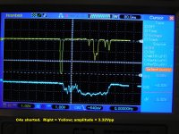
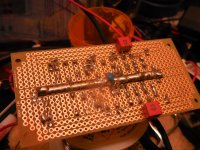
Here are the C4s shorted pics Hans. One is a Lift and the other is a Lower. I forgot which but you can see the R&L, close/open sequence shift in time, FWIW. There were large static offsets. One was ~-190mVrms and the other ~+20mVrms. Overall, not too pretty so the C4s have to stay. I "always" see them even in the 2-part RIAA EQ circuits.
I'm listening again to the 1656 tonight with the original 220R + 15pF polystyrene dampers installed. Have made no final choice and am listening for any artifact of the damper network. The OPA627 has some kind of subtle sonic magic that others notice as well.
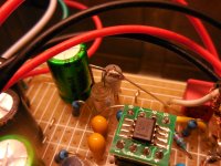
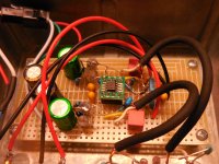
There is something funny about the 1656 in this circuit. I built it twice. The 2nd time I reduced the geometry and acreage; shortened all through-the-air jumper connections, replaced a large 160V polystyrene with two smaller, 33V in parallel and stood up vertically; replaced the other large poly with two selected Wima MKP10 boxes in-parallel; redid the power distribution and ran Gnd down the center as one fat bus bar vs. split, side-to-side, etc. No joy. THUMP was still there 😕
Attachments

Did the second 1656 amplifier include the dampers? Or did you build it to find out if you could do without dampers with a more compact layout?
@johnc124 Suppose you made a voltage follower (a phono amplifier is essentially a voltage follower at high frequencies) with an OPA1656 with a PCB with picture perfect layout, SMD decoupling caps right at the supply pins and so on. Could its input impedance then still have a negative real part over some part of its frequency range or does it require a less than ideal board for that?
Last edited:
[...]
I'm listening again to the 1656 tonight with the original 220R + 15pF polystyrene dampers installed. Have made no final choice and am listening for any artifact of the damper network. The OPA627 has some kind of subtle sonic magic that others notice as well.
You might want to look at the OPA828, which TI touts as the next generation OPA627.
O.k. Nothing new, confirming that C4 is taking no part in the thump reactions.Here are the C4s shorted pics Hans.
So keep it as before.
About the different behaviour between the two channels without damping, could this be caused by the fact that one channel on your Cart is connected between the cold side and the Cart’s housing and thus also via the arm to the TT chassis while the other channel goes floating to your preamp ?
And there is also a separate wire going from your TT’s chassis to your preamp housing, true ?
Hans

Any comment on the RF immunity R3/C3 combo in the above post.
The schematic shown is for a bipolar op amp. The FET input op amp is inherently more immune to RF due to the linearity of the FET which will not readily detect RF.
opa1656 has offset voltage that varies with the input Z. 47k no cart 1500 ohms cart in
you are hearing a few mV of offset being amplified to a few volts when the TT switches.
this is what a input capacitor removes.
you are hearing a few mV of offset being amplified to a few volts when the TT switches.
this is what a input capacitor removes.
The cable is either driven by a cart or by a shorted cart, the OPA1656 input bias current is supposed to be typically 10 pA and a 15 pF-220 ohm RC series network shunted across the input much reduces the thump. If it were due to the bias current, you should get a voltage change of about 1000*1500 ohm*10 pA = 15 uV and the 220 ohm-15 pF network shouldn't have any influence at all.
Last edited:
Did the second 1656 amplifier include the dampers? Or did you build it to find out if you could do without dampers with a more compact layout?
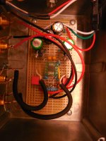
All of the experiments and trials were using the second build. Only the original pics and diagrams were of the first go. Everything test-wise pertains to the 2nd build. There was no real change in the 1656's behavior in a new environment so I saw no reason to mention it. The attached is as it's been for a while now.
I may swap in the #1 build now that I have a silver bullet just b/c it is all polystyrene vs. a hybrid. But that can wait.
Attachments

O.k. Nothing new, confirming that C4 is taking no part in the thump reactions.
So keep it as before.
About the different behaviour between the two channels without damping, could this be caused by the fact that one channel on your Cart is connected between the cold side and the Cart’s housing and thus also via the arm to the TT chassis while the other channel goes floating to your preamp ?
And there is also a separate wire going from your TT’s chassis to your preamp housing, true ?
Hans
I'd have to track down why I saw a low-ohms reading between one channel's shield and the TT's gnd wire. More tasks for me!
Yes there is always a piece of ordinary hook-up wire out the back of a TT to be connected to the Phono Gnd at the preamp. Never knew what this did but if not connected you know it.
I like your description of the damper!
Ha! Now I know you read e v e r y w o r d...
I'd have to track down why I saw a low-ohms reading between one channel's shield and the TT's gnd wire. More tasks for me!
Yes there is always a piece of ordinary hook-up wire out the back of a TT to be connected to the Phono Gnd at the preamp. Never knew what this did but if not connected you know it.
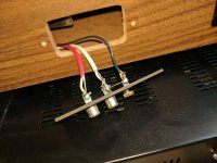
Like the attached. I think they did that in my TT.
Attachments
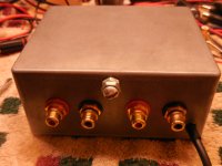
You are using a separate wire from preamp case to TT chassis, right?
So because of that important wire, cut that short piece of wire in your picture connecting the TT chassis to one of the two RCA sockets.
Then measure the still disconnected TT between the cold side of both RCA sockets and TT chassis whether there is still a connection.
If not, both channels are now floating and should give the same response without Diazepam.
Hans
- Home
- Source & Line
- Analogue Source
- OPA1656 Phono Preamp: Split from OPA1656 thread