It seems you're not the first one Full Range...
http://www.diyaudio.com/forums/tubes-valves/110458-magnetic-shields-transformers-2.html#post1331218
Great info on that link
Many thanks
I'm looking at what possibilities there are to fit two pieces of 250-300VA trannies and PSU-boards into the 300/400 mm Slim Line chassis.
(Toroidy trannies and Tea-Bag's boards.)
Would like to hear your comments on if you think the 300mm would work, and what layout you think would be best? Any benefit that the Fet's probably will have better temperature matching, due to the 300mm's having solid heat sinks?
//Ronny
(Toroidy trannies and Tea-Bag's boards.)
An externally hosted image should be here but it was not working when we last tested it.
An externally hosted image should be here but it was not working when we last tested it.
An externally hosted image should be here but it was not working when we last tested it.
An externally hosted image should be here but it was not working when we last tested it.
An externally hosted image should be here but it was not working when we last tested it.
Would like to hear your comments on if you think the 300mm would work, and what layout you think would be best? Any benefit that the Fet's probably will have better temperature matching, due to the 300mm's having solid heat sinks?
//Ronny
Last edited:
I'm looking at what possibilities there are to fit two pieces of 250-300VA trannies and PSU-boards into the 300/400 mm Slim Line chassis.
(Toroidy trannies and Tea-Bag's boards.)
An externally hosted image should be here but it was not working when we last tested it.
An externally hosted image should be here but it was not working when we last tested it.
An externally hosted image should be here but it was not working when we last tested it.
An externally hosted image should be here but it was not working when we last tested it.
An externally hosted image should be here but it was not working when we last tested it.
Would like to hear your comments on if you think the 300mm would work, and what layout you think would be best? Any benefit that the Fet's probably will have better temperature matching, due to the 300mm's having solid heat sinks?
//Ronny
Hi Ronnie,
I used the 400mm in my M2 build, I found I needed the extra length to fit everything in without any drama. I used the DIY psu and a 400va transformer a D there wasn't a lot of room left. I also used Grimbdrg's boards which are longer than. Teabag's and I needed the length.
Paul
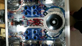
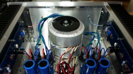
I also used Grimberg's PCBs 😀 and individual power supplies for each channel, all assembled in a hand crafted case. The internal dimensions are: 11.75" width x 13.62" length x 5.87" height (298 mm x 346 mm x 149 mm).
Here are some pictures which may help you.
Here are some pictures which may help you.
Attachments
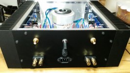

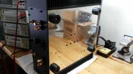
I know you guys enjoy porn, but decorum demands at least one picture that does not display the intimate parts. Here it is. 🙂
Also notice how good the bottom plate looks with all screws flush, except for the transformers' bolt.
Also notice how good the bottom plate looks with all screws flush, except for the transformers' bolt.
Attachments

Also notice how good the bottom plate looks....
Noticed looks like beauty work !
Applause 🙂

Hi Ronnie,
I used the 400mm in my M2 build, I found I needed the extra length to fit everything in without any drama. I used the DIY psu and a 400va transformer a D there wasn't a lot of room left. I also used Grimbdrg's boards which are longer than. Teabag's and I needed the length.
Paul
I also used Grimberg's PCBs 😀 and individual power supplies for each channel, all assembled in a hand crafted case. The internal dimensions are: 11.75" width x 13.62" length x 5.87" height (298 mm x 346 mm x 149 mm).
Here are some pictures which may help you.
Thanks for your inputs!
I'm not worried about room per se, which can mostly be solved some how. I'm more worried about other problems, like interference leading to humming. But I realize there is no definite answer to that question.
That IS a beautiful case, and build, Grimberg! I wonder about your looped leads. Have you done it like that just keep them long, or is there any other reason?
//Ronny
I always keep the leads initially long in case I have to rotate the transformer to reduce induced noise. In the case of the M2, the first time I started the amplifier after the whole case was assembled, it was absolutely quiet. I decided to just leave the long leads tidy with the help of zip ties.
Regarding the humming noise, many people reported successful builds using either the PCBs I or Tea-bag designed. Only one person complained about persistent hum. Incidentally that is also the person who did not assemble the PCB himself and claimed to be sure that all wiring and mechanical assembly were absolutely correct. That may be the case, but the noise is still present.
In my view resolving a problem must start with the right attitude. Assuming that the problem is restricted to one area, without systematically probing all others, is not a positive approach to problem solving.
To improve your chances of success, start one channel, adjust it and listen to it. Do the same with the other. Next, connect both channels and, if you are using a single PSU, adjust both again because of the voltage drop, and listen to them. At that point, if you have an issue it will manifest itself. Noise? Go back and locate which step caused it. Satisfied? Move the parts to their approximate final location. It is easy to do with a hifi2000 case or a custom built one like mine. Move the heat sinks next to the bottom and back plates, so all the parts look almost as if the case is fully assembled. If necessary, use books to prop up the back panel. In my experience, if at that point the amplifier sounds as expected, you can safely finish your assembly and pour the wine in the decanter. 🙂
No mystery or secret rituals, just common sense.
Hi Grimberg,
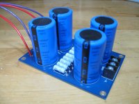
Is that PSU pcb also your own design? I've been looking for something compact
like that.
Thanks,
Dennis
Is that PSU pcb also your own design? I've been looking for something compact
like that.
Thanks,
Dennis
Dennis,
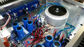
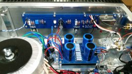
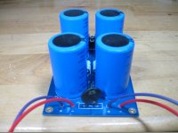
The board layout is my design. The schematic is just a regular CRC PSU.
I wanted to fit two boards in a case to have separate PSUs for each channel. I use four capacitors of 33mF each. I also added the thermistor to the PCB and connected one of its leads to the four mounting holes.
The board layout is my design. The schematic is just a regular CRC PSU.
I wanted to fit two boards in a case to have separate PSUs for each channel. I use four capacitors of 33mF each. I also added the thermistor to the PCB and connected one of its leads to the four mounting holes.
Attachments
Regarding the humming noise, many people reported successful builds using either the PCBs I or Tea-bag designed. Only one person complained about persistent hum. Incidentally that is also the person who did not assemble the PCB himself and claimed to be sure that all wiring and mechanical assembly were absolutely correct. That may be the case, but the noise is still present.
In my view resolving a problem must start with the right attitude. Assuming that the problem is restricted to one area, without systematically probing all others, is not a positive approach to problem solving.
To improve your chances of success, start one channel, adjust it and listen to it. Do the same with the other. Next, connect both channels and, if you are using a single PSU, adjust both again because of the voltage drop, and listen to them. At that point, if you have an issue it will manifest itself. Noise? Go back and locate which step caused it. Satisfied? Move the parts to their approximate final location. It is easy to do with a hifi2000 case or a custom built one like mine. Move the heat sinks next to the bottom and back plates, so all the parts look almost as if the case is fully assembled. If necessary, use books to prop up the back panel. In my experience, if at that point the amplifier sounds as expected, you can safely finish your assembly and pour the wine in the decanter. 🙂
No mystery or secret rituals, just common sense.
With regards to my build and noting the above post I consider my M2 a successful build with only one issue that was not related to the actual kit or the PCB assembly
"However I do agree with Grimberg that one should test at every stage and especially at power up to sort out any problems that present themselves " at that time ( if any ) and sort them out
One must consider that I have many work related free time constraints that restrict my hands on time with the amplifier
The sulutions tried to sort out the hum issue, started with the easiest to the hardest
Eventually we found the culprit as the toroidal itself - I also feel that the toroidal installed in my M2 may have been manufactured poorly or let slip through quality testing ? Who knows
Thing is we all learn from our collective experiences and In my case I will use an old saying
Once bitten Twice shy
I ain't gonna let that happen again in a future build
FR
On the other hand, there's no better way of learning than problem solving, as long as you keep calm and progress logically. Which I have the impression you did Full Range.
I'm thankfully taking your advice Grimberg! And those PSU boards look very neat, by the way!
//Ronny
I'm thankfully taking your advice Grimberg! And those PSU boards look very neat, by the way!
//Ronny
I have designed two mechanical versions of a sphincter for post surgery prostate cancer sufferers
That was easier than finding the hum 😱
That was easier than finding the hum 😱
I have designed two mechanical versions of a sphincter for post surgery prostate cancer sufferers
That was easier than finding the hum 😱
That is without a doubt, one of the more unexpected analogy's I have seen on this forum. 😛
That is without a doubt, one of the more unexpected analogy's I have seen on this forum. 😛
Indeed! =D
Dennis,
The board layout is my design. The schematic is just a regular CRC PSU.
I wanted to fit two boards in a case to have separate PSUs for each channel. I use four capacitors of 33mF each. I also added the thermistor to the PCB and connected one of its leads to the four mounting holes.
Thanks for the details.
BTW, what do you use to separate the transformers when you stack them
together? I'm may need to do that for a vfet2 build but am unsure what
works well in practice.
Thanks,
Dennis
Thanks for the details.
BTW, what do you use to separate the transformers when you stack them
together? I'm may need to do that for a vfet2 build but am unsure what
works well in practice.
Thanks,
Dennis
Insofar as I understand it, you only need a rubber spacer between the two transfo's. Papa’s Koan (M)2 , an amp for living room | Zen Mod Blog for the ZM approach (i love re-purposing 🙂 )
Last edited:
- Home
- Amplifiers
- Pass Labs
- Official M2 schematic