>The amp hums even if the RCA interconnects are not attached/connected
from the Nakamichi CA5 Pre to the M2 .
You did not completely answer my question.
from the Nakamichi CA5 Pre to the M2 .
You did not completely answer my question.
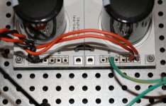
which C bank pcb is that ?
unscrew it , give us picture of copper side , mark all wire points
Did you jumper the grounds together on the boards?
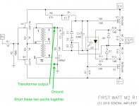
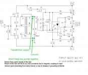
Also, for FR's humming problem, what happens when you short the output
of the transformer to ground?
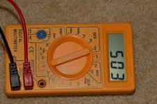
Test 1 - while toroidal is connected to the Bridge rectifier and earth
The Right channel shows a steady 445 on both AC output wires
The Left channel shows a slowly rising number that stops at 503 on both AC output wires
Test 2 - free cable of toroidal to earth ( not connected to bridge rectifier )
The Right channel shows a steady 473 on both AC output wires
The Left channel shows a slowly rising number that stops at 530 on both AC output wires
FR
Attachments

which C bank pcb is that ?
unscrew it , give us picture of copper side , mark all wire points
Tea Bag PSU
Sorry no time to pull it apart ZM as I am on 24 hr call, and the phone wont stop ringing 😱
However here is closeup of the wire entry points and the jumper cable to join the 2 boards together ( hope that is enough )
FR
Attachments
FR
You set the DMM to buzzer/diode tester. The display then shows the forward voltage drop at a test voltage of a few volts. This DMM can not measure AC ripple in the range you need.
I am sure Nelson referred to the audio transformer output to be shorted, not the mains transformer.
What is your output DC?
FR
You set the DMM to buzzer/diode tester. The display then shows the forward voltage drop at a test voltage of a few volts. This DMM can not measure AC ripple in the range you need.
I am sure Nelson referred to the audio transformer output to be shorted, not the mains transformer.
What is your output DC?
Now I feel like a Dodo 😱
A common mechanical engineering trait when presented with electrical terms named the same
Can't do anymore tests
The amp is packed up ready to go to the technician tomorrow morning
So I will ask him to do the test
I think Nelson wanted me to test this ( see drawing ) a little late I know but hopefully redeemed myself 😎
FR
Attachments
that picture (post @1725) is not enough , because I'm not familiar with that pcb and we need to see traces (if possible ) to figure did you got gnd take-in and take-out from proper place
yes , Pa meant exactly that , result of that test will tell do you have problems due to magnetic coupling to input xformer (junk emanating from mains Donut) or due to mistake in grounding scheme
yes , Pa meant exactly that , result of that test will tell do you have problems due to magnetic coupling to input xformer (junk emanating from mains Donut) or due to mistake in grounding scheme
that picture (post @1725) is not enough , because I'm not familiar with that pcb and we need to see traces (if possible ) to figure did you got gnd take-in and take-out from proper place
yes , Pa meant exactly that , result of that test will tell do you have problems due to magnetic coupling to input xformer (junk emanating from mains Donut) or due to mistake in grounding scheme
Thanks for the explanation ZM
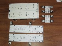
You are in luck
I have a photo from the start of the build
However I don't think you can see much of the trace
FR
Attachments
.....
However I don't think you can see much of the trace
FR
nope
I am about to embark on my first Pass amp build...an M2 using Teabag's boards. My intention is to use a large box from the Audiostore.
I notice that many members build a variety of Pass amps and that the cost is mainly in the cabinet plus power supply.
So as to allow for other amps being built at strict cost control it is my intention to have the boards mounted on copper heat-spreader plates which can easily be removed thereby allowing a different set of amp boards on their own heat-spreader boards - to be mounted using just the one cabinet with heatsinks.
Further, is there sense in having an external power supply - in its own cabinet - which could further facilitate ease of change. The advantage (to me anyway being old and getting older and having bad arm tendons - from too much fishing - ) is that two lugging exercises are easier than one session with a single but much heavier box!
What are the pitfalls of these ideas in practice? Many thanks, most especially to Nelson Pass.
Last edited:
I also had same idea with yours previously to use copper heatspreader, but it was not an easy and fun things to do because at the end you need to rewire everything.
so my solusion is to build separate chassis for psu (toroid + cap bank) and get each amplifier with dedicated chassis. When you want to change amps, you only need to plug-unplug for psu (using neutrik powerCon) and rca input, it's so simple.
you can check on my signature for your build idea.
so my solusion is to build separate chassis for psu (toroid + cap bank) and get each amplifier with dedicated chassis. When you want to change amps, you only need to plug-unplug for psu (using neutrik powerCon) and rca input, it's so simple.
you can check on my signature for your build idea.
After building 5 amps with the power supply in the case I've built the last 2 using an external power supply. Better in many ways. They are smaller and lighter, so easier moving them around, like you said. Cheaper. No noise from the transformer radiating into the amp. No downside for me.
Also, for FR's humming problem, what happens when you short the output
of the transformer to ground?
yes , Pa meant exactly that , result of that test will tell do you have problems due to magnetic coupling to input xformer (junk emanating from mains Donut) or due to mistake in grounding scheme
Mr Pass & ZM
I visited the technician today and I asked him to do this test ( as per drawing )
And I have an answer
The Hum STOPPED
He performed many other tests without success, indicating that my PSU may possibly need to have more capacitance / with a question mark ?
Haven't proceeded in any direction until I checked in with you first
FR
Attachments
......
The Hum STOPPED
.......
which means that hum is magnetically induced in input xformers
next step/test - move toroids from case ; if hum is gone and amp sings ...... you need plenty of screening (both input and mains xformer) ...... or even moving Donut to separate box , in case it is too stubborn
Thanks ZM
During my visit to the tech, it was suggested to do a trial power up with batteries to test this by alleviating the AC power
But it may be best to plan for a separate enclosure to house the power section
I have had a look in the DIY store but finding a non heat sink box to match the dimensions of my 5U Deluxe is proving elusive
FR
is it possible to make balance M2? F4,F5,BA3 already proven but I dont build them. I'm thinking to build another M2 and X them, it seems getting another teabag kits will not require too much $. Maybe only need to add another psu toroid and make them paralel to give more VA.
it will be powering dual woofer for my OB
it will be powering dual woofer for my OB
Thanks ZM
During my visit to the tech, it was suggested to do a trial power up with batteries to test this by alleviating the AC power
But it may be best to plan for a separate enclosure to house the power section
I have had a look in the DIY store but finding a non heat sink box to match the dimensions of my 5U Deluxe is proving elusive
FR
You may just want to try another PS transformer that is shielded. Antek sells them and I have used both the shielded and unshielded Anteks without noise. Maybe some builders of the M2 here in your part of the country on this froum can suggest what they have used.
is it possible to make balance M2? F4,F5,BA3 already proven but I dont build them. I'm thinking to build another M2 and X them, it seems getting another teabag kits will not require too much $. Maybe only need to add another psu toroid and make them paralel to give more VA.
it will be powering dual woofer for my OB
I believe you'll get more in paralleling them ( or , in case you have more drivers per side - having one amp channel to one driver ?) than bridging them in any way
remember that M2 is having just one pair of outputs ....... and in case of bridge , each output half is seeing half of load
- Home
- Amplifiers
- Pass Labs
- Official M2 schematic