bomellberg;
It's not very important.
I don't see the problem in having 2 times 5mm extra track path in this kind of amplifier. If so I had made the layout totally diffrent.
Remember that many amplifiers has the output devices fitted outside the PCB with wire connections between the devices and the PCB.........
It's not very important.
I don't see the problem in having 2 times 5mm extra track path in this kind of amplifier. If so I had made the layout totally diffrent.
Remember that many amplifiers has the output devices fitted outside the PCB with wire connections between the devices and the PCB.........
Thanks for the reply.
Just to be clear: what's not important, to lift them or to keep the paths short? I have already mounted them 5-10 mm above the pcb as per the instructions. I guess I'll just keep them there.
Also, I'm having some trouble finding the 33pF FKP2 caps. Farnell has 1000V-variants, but they are 4,5mm thick and won't fit (even though the data sheet says 2,5 mm, grrrr).
bomellberg;
Both 😉
It's not important to keep paths short in this type of amp (this is not a 1MHz amp), and it's not important to lift power resistors, however 30 years with working in electronics has learned me always to lift power devices from the PCB. Remember their specifications are rated in free air. 😉
Just to be clear: what's not important, to lift them or to keep the paths short? I have already mounted them 5-10 mm above the pcb as per the instructions.
Both 😉
It's not important to keep paths short in this type of amp (this is not a 1MHz amp), and it's not important to lift power resistors, however 30 years with working in electronics has learned me always to lift power devices from the PCB. Remember their specifications are rated in free air. 😉
One more question more general LYNX setup : since the LYNX present a OPA627 as entry stage, i suppose he don't need to feed by a high preamp gain, right? What about the volume control? Is the LYNX enough immun to impedance variation of a simple ALPS (for exemple) poty? Or will it benefical to insert à buffer (PASS B1) for example) between poty and power amp???
To make the rooting work do you see an objection to usethis 100nf capacitor in 2F4 dielectric. The leads permit through all rooting.
Marc
To make the rooting work do you see an objection to usethis 100nf capacitor in 2F4 dielectric. The leads permit through all rooting.
Marc
Idefixes;
It's not the type of Opamp in the input that sets the gain of the amplifier. Gain is set by the two feedback resistors.
You can use a quality 47k pot or a buffer in the input. I just use a pot.
I see no problem using AVX caps.
It's not the type of Opamp in the input that sets the gain of the amplifier. Gain is set by the two feedback resistors.
You can use a quality 47k pot or a buffer in the input. I just use a pot.
I see no problem using AVX caps.
ACD said:Idefixes;
It's not the type of Opamp in the input that sets the gain of the amplifier. Gain is set by the two feedback resistors.
You can use a quality 47k pot or a buffer in the input. I just use a pot.
I see no problem using AVX caps.
I know that about the gain, but my question was more about the LYNX input sensibilty/inpedance due the presence of the OPA627 at this stage.
Marc
i suppose he don't need to feed by a high preamp gain, right?
I know that about the gain, but my question was more about the LYNX input sensibilty/inpedance due the presence of the OPA627 at this stage.
Please look
 at the schematic for the LYNX and the datasheet for the OPA627. As the OPA627 has an input impedance of 10^13 Ohm, the input impedance is mainly set by R101 and R102 plus the Volume pot if you use one. Resulting input impedance with a 47 KOhm Volume pot will be app. 33K.
All FET opamps has a very high input impedance, so the result will be almost the same what ever FET opamp you use................
ACD said:
Please look
All FET opamps has a very high input impedance, so the result will be almost the same what ever FET opamp you use................
Thanks for answer and for time you take to answer on every (silly???) question. I' m on puting parts together from my stock to see what I need to buy.
best regards. Marc
op-amp
halo Jan
can i replace the op-amp (original OPA 627/134 , previously i use LF356) with AD797 ?
i just found this op amp in my city.
i cannot find OPA134.
The Amp still play in my room!
with rock song.
Thank's
La Ode
halo Jan
can i replace the op-amp (original OPA 627/134 , previously i use LF356) with AD797 ?
i just found this op amp in my city.
i cannot find OPA134.
The Amp still play in my room!
with rock song.
Thank's
La Ode
crt;
I have never tried the AD797 in the LYNX but in many other circuits. Has shown to be very stable so give it a try 😉
I have never tried the AD797 in the LYNX but in many other circuits. Has shown to be very stable so give it a try 😉
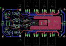
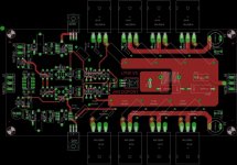
I work last day on redrawn ACD work on Lynx to build localy PCB. I do it with Eagle. For moment this work needs to be seriously verify. I put only image files. Later after testing i will share eagle file with who's interesting.
But note this disclamer :
- The LYNX circuit and PCB layout provided here is only for non-commercial diy build and use! You are not allowed to make and sell copy PCBs! You are allowed to make your own PCBs for personal use, but please accept that in that case Ithat ACD do not provide any support as me! This work is a personnaly work on parts placement with respecting ACD work, i wanted only to avoid the use of metalized hole since i haven't accept on its.
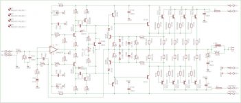
First the schematic redrawn with MJL3281A/MJL1302A output device
But note this disclamer :
- The LYNX circuit and PCB layout provided here is only for non-commercial diy build and use! You are not allowed to make and sell copy PCBs! You are allowed to make your own PCBs for personal use, but please accept that in that case Ithat ACD do not provide any support as me! This work is a personnaly work on parts placement with respecting ACD work, i wanted only to avoid the use of metalized hole since i haven't accept on its.
First the schematic redrawn with MJL3281A/MJL1302A output device
Attachments

ACD said:Idefixes;
Nice work, Marc
Kindly remove my name from the PCB unless we share the same name 😉
No soucy i juste forget It, i see it to late as it was posted
I will remove it on next update.
Marc
I'm having a hard time finding the 2,5mm thick FKP2 33pF caps.
I ordered the 1000V-variant from Farnell but it's 4,5mm thick and won't fit (unless I put it on the solder side...) Also, at WIMAs homepage, the 2,5mm variants are gone, see this:
http://www.wima.com/EN/fkp2ue.htm
Do you have any tips on a replacement cap?
/Bo
I ordered the 1000V-variant from Farnell but it's 4,5mm thick and won't fit (unless I put it on the solder side...) Also, at WIMAs homepage, the 2,5mm variants are gone, see this:
http://www.wima.com/EN/fkp2ue.htm
Do you have any tips on a replacement cap?
/Bo
- Status
- Not open for further replies.
- Home
- Amplifiers
- Solid State
- Official LYNX Power Amp builder’s thread