Hi Pico, which output impedance you have with this mosfet?
Haven't measured it yet.
Probably this is the most important problem that could it bring.
Thanks for your answer.
Bst RGRDS.
Thanks for your answer.
Bst RGRDS.
I need to remeasure the device again, I just realised a small error, which may have significantly affected the result
Not yet available but will definitely be available soon.
I'll find out when they are ramping up production to release them publicly.
It can't be too far away. I'd say within the next 6 months as a guess.
You might be surprised at what I have on my shelf. Even if it's the same,
it would be good to have them available.
😎
You might be surprised at what I have on my shelf.
😎
I wouldn't be at all surprised if you had a 10MW Gyroklystron!
(c) Vincent Spanier Photography
Attachments


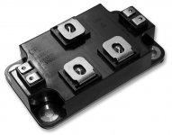
CREE CAS100H12AM1
Reminds me something 😉
CAS100H12AM1 - CREE - Bipolar (BJT) Single Transistor, Dual N Channel, 168 A, 1.2 kV, 0.016 ohm, 20 V, 2.6 V | Farnell element14 Israel
Reminds me something 😉
CAS100H12AM1 - CREE - Bipolar (BJT) Single Transistor, Dual N Channel, 168 A, 1.2 kV, 0.016 ohm, 20 V, 2.6 V | Farnell element14 Israel
Attachments


Could one replace the two IRF's in the F6 with just one of these?
I do not know I got them as a gift
I got one of each
Too bad it's not a pair of each. But for such a gift I do not complain
I have found a interesting project to take advantage of them
( I probably use them on one of my projects on power supply)
jfet SiC Cascode


Attachments
Last edited:
I couldn't import the spice model of c2m1000170d. while importing this shows an error while compiling. could anyone help me in debugging the error.??
I know I'm digging up an old thread here but with the last few puddles of Semisouth SiC jfets drying up, was there any continued interest in finding new SiC candidates to use? I know there are a couple of amps built with Cree devices and the spotlight is all on transformers now (not the movies) but I have an F2 from my own layout built and running (runs very nicely thank you Papa!!!) and have a set of the GB F2 boards stashed away so thought I would try building an F2J variant.
Unfortunately I never knew much about electrical engineering to begin with and have forgotten pretty much everything after raising 2 kids so I haven't got a clue what to look for or what to modify to make this work.
All the Cree devices mentioned in the thread are out of stock (C2M devices) but there are some C3M pieces available and under $20 ea. I've read this thread from start to finish a few times and understand that the important parameters to look for are transconductance, power dissipation, input capacitance. I have no idea what to look for in the curve traces. Based on that I narrowed down my candidates and want to ask if the Cree C3M0120090D looks any good? Here is the datasheet:
C3M0120090D datasheet https://www.wolfspeed.com/media/downloads/824/C3M0120090D.pdf
Transconductance (gfs@ 20V, 15A) - 7.7 or 6.7@150C
Input Capacitance - 350pF
Power dissipation - 97W
I know it would be easiest to just build it with unobtanium (Semisouth) but I never had any of those to begin with and even if I were to buy some, I would rather save them for future considerations (J2 perhaps or SIT maybe??? A boy can dream right?). Any advice is very much appreciated and thanks again to Papa for his generosity and for feeding this DIY addiction!!!
These would be alternate candidates for a high current cascoded stage,
along the lines of the Jfet in the F3, as you can see low Drain impedance
at low Drain voltages and high current, allowing cascode modulation.
along the lines of the Jfet in the F3, as you can see low Drain impedance
at low Drain voltages and high current, allowing cascode modulation.
Ok so I went away and did some more reading and since we're looking to replace the output device in the F2 to make it into an F2J variant, we need something else (not the C3M0120090D but thank you Papa for pointing out it's use in a high current cascode stage).
I'm still not sure what to look for but the next candidate is the C3M0280090D
Datasheet
https://www.wolfspeed.com/media/downloads/825/C3M0280090D.pdf
Rds - 0.28 Ohms compared to 0.18 for IRFP240
Ciss - 150 pF
Transconductance - 3.6 compared to 6.9 for IRFP240
Power Dissipation - 54W ... this is low
For F2J, would it be good enough to parallel 2 of these in place of the output mosfet? Rds gets halved, Ciss goes to 300pF, transconductance doubles? and power dissipation is no longer a problem with the F2 chewing up 75W per side. I don't know what else to look for or if any of the other parameters makes this a suitable candidate but if anyone can chime in I would greatly appreciate it! Thanks for listening 😀
Many have explored these options before including myself. The results won’t be and F2J or or F2.At the end you will spend the money you are trying to save one something else, Perhaps even more.
It depends on what your objectives are. If you are an amp designer by all means go for it. But if you are trying to copy Papa’s design ( I am) just use the original components he selected.
It depends on what your objectives are. If you are an amp designer by all means go for it. But if you are trying to copy Papa’s design ( I am) just use the original components he selected.
Thanks for the rationalization Kinku. It makes sense why this thread faded away when you put it that way. I like my F2 too much to take it apart to build an F2J. I would build another amp so it's definitely not any attempt to save money (it's a sickness really). At the end of the day, it's this burning curiosity to find out what it sounds like and how it's different and better than the F2 but I was hoping to find a way that wouldn't require me to sacrifice an endangered species (Semisouth jfets). As you stated though, it won't be and F2J in the end so completely misses the point. Thanks for bringing me back to reality.
I thought I would help you out and save some bucks too. I can attest that F2J is a bit better transparent than F2 when it comes to listening experience. It does not by any means imply that F2 is not a good amp. I liked it too but will pick F2J over F2. I think Papa also measure and prove why is it so. Lower distortion with JFET!
But remember to have a buffer stage before F2J as input impedence is way lower than F2.
I am trying to put my F2J amp into its chassis for past two weeks and never got to it. I end up listening to it and slack out with the task.
But remember to have a buffer stage before F2J as input impedence is way lower than F2.
I am trying to put my F2J amp into its chassis for past two weeks and never got to it. I end up listening to it and slack out with the task.
The expectations of performance on the F2 are such that it might be just
fine to use that part. For all I know, it might sound better.
fine to use that part. For all I know, it might sound better.
Last edited:
Is this one depletion mode? Mostly negative gate to source voltage?
https://www.mouser.com/datasheet/2/827/DS_UJ3N120070K3S-1530204.pdf
https://www.mouser.com/datasheet/2/827/DS_UJ3N120070K3S-1530204.pdf
- Home
- Amplifiers
- Pass Labs
- new SiC JFETs?