Hello Zen Mod and umut1001.
You [Zen Mod] have a valuable approach for testing.
The Description of the device reads like SJDP120R085; hi power switching; except the device is an enhancement type. I'd use it in Class aP [switching; Class B] like I've done recently with [R085]; with a concern about the magnitude and impact of its input capacitance. How will it compare with SJEP120R100?; which maybe a comparator. I have four [R100s] from the great days of F6 to test in Class aP.
Best wishes
Anton
The whole interpretation of the mis-fit in use for audio lies in the intepretation of the graph; but that graph is made for the intended switching purpose.
Better: make the Michael Rotachcher test rig for SITs and test them [& adapt the bias supply??], as long as you have his XY-input scope.
I would not be surprised that at the 300mA-1 amp area there is a very interesting operating area - just like the low end of the lovoltechs -. At least when I looked into the datasheet I provisionally made that interpolation: potential benefit.
Better: make the Michael Rotachcher test rig for SITs and test them [& adapt the bias supply??], as long as you have his XY-input scope.
I still have to make it, on the waiting list 
I would not be surprised that at the 300mA-1 amp area there is a very interesting operating area - just like the low end of the lovoltechs -. At least when I looked into the datasheet I provisionally made that interpolation: potential benefit.
The whole interpretation of the mis-fit in use for audio lies in the intepretation of the graph; but that graph is made for the intended switching purpose.
Better: make the Michael Rotachcher test rig for SITs and test them [& adapt the bias supply??], as long as you have his XY-input scope.
I still have to make it, on the waiting list
I would not be surprised that at the 300mA-1 amp area there is a very interesting operating area - just like the low end of the lovoltechs -. At least when I looked into the datasheet I provisionally made that interpolation: potential benefit.
Hi.I searched but could not find Michael Rotachcher test rig for SITs.
Could you send me a link?Thanks in advance
Here is the link for the $20 costing tracer but you need to buy that special scope 😉
The Frankentracer (scroll down)
Articles | AudioMaker
Video
Frankentracer: $20 SIT Curve Tracer Part One | AudioMaker
have fun
The Frankentracer (scroll down)
Articles | AudioMaker
Video
Frankentracer: $20 SIT Curve Tracer Part One | AudioMaker
have fun
Last edited:
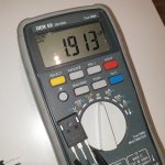
Hi.I measured VGS of UJ3C120040K3S . I connceted G and S and resistor is 2k36 and used notebook power supply 19,5v. I measured 4.69v and 4.71v . I also measured IRFP240 in same circuit and found 3,42v and 3,47v.
care to post a sketch of your arrangement?
it would be OK/clear that you did wrote "connected G and D" , and ve could compute that current was (19V5-4V7)/2K36=6mA3
try that with 15R/50W, and transistor heatsinked
it would be OK/clear that you did wrote "connected G and D" , and ve could compute that current was (19V5-4V7)/2K36=6mA3
try that with 15R/50W, and transistor heatsinked
Yes i see VGS match with 15v on diyaudio page
https://www.diyaudio.com/community/threads/nelson-pass-easy-peasy-mosfet-vgs-measurement.299546/but i do not have a variable source right now and i used notebook charger which is 19,5v.
I have this in my store
https://www.ebay.com/itm/175019393476I think i can connect it asap.
Yes i will try. I hope they work.
Sorry for poor circuit picture
I am not sure capacitance of GS can be measured like that but it may give an idea maybe. UJ3C120040K3S gs capacity seems about 5% lower than IRFP240.And power is about 3x of IRFP240 according to datasheets
Attachments
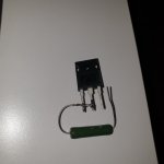
yes, as you did it with that smaller (green) resistor, most right free pin is S, goes to negative, D and S shorted to resistor, other end of resistor goes to positive 19V5
heatsink both 25W resistor and SIC while measuring
you'll have approx 15W of heat in resistor, 4W or so in SIC, expected current in range of 1A
when you're done, we'll compute all from Ugs
heatsink both 25W resistor and SIC while measuring
you'll have approx 15W of heat in resistor, 4W or so in SIC, expected current in range of 1A
when you're done, we'll compute all from Ugs
Datasheet for UJ3C120040K3S - it's a cascoded SIC fet but normally off device (enhancement), not depletion so not candidate for DEF
UnitedSIC Datasheet - UJ3C120040K3S
Expected Vgs(th) is between 5V (range from 4-6).
UnitedSIC Datasheet - UJ3C120040K3S
Expected Vgs(th) is between 5V (range from 4-6).
uniqueness of DEF arrangement is really not resulting from "depletion", but from resistive nature of SIT/FET part combined with regular mosfet
result is wakoo transfer characteristic, best illustrated with unique current distribution between these two parts
as I did show in Babelfish M25-SET, where I used Schaded mosfet , same behavior, thus same transfer characteristic is achieved in that way too
so, that being case of both enhanced type of parts (Schaded mosfet still being enhanced) .......
I just built a Frankentracer & since I don't have an oscilloscope or a variac yet, I just played with the gate bias point (the voltage between the gate and source) at which I started getting Drain to Source conductance, which you can detect with just a voltmeter across the 1R power resistor. I tested two of 2SK180 and two of THF-51S and to my pleasant surprise all four started conducting right around -5.5V to -5.7V.Here is the link for the $20 costing tracer but you need to buy that special scope 😉
The Frankentracer (scroll down)
Articles | AudioMaker
Video
Frankentracer: $20 SIT Curve Tracer Part One | AudioMaker
have fun
I don't think a Frankentracer would work for testing this UJ3C120040K3S device though? This device is not depletion mode like a SIT (it's called "normally-off" in the spec sheet), nor is the threshold Vgs negative. The Frankentracer makes gate DC voltages from zero to about -25V, not positive gate voltages, at least in standard configuration. And the drain to source current appears to be mostly AC.
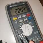
Hi.I have made another test.Test resistor is about 15,4 ohm (serial 7,65+7,75ohms toshiba cement 25w each i found in storehouse) Power supply around19,33 volts. Vgs is 5,33volts as i measured.yes, as you did it with that smaller (green) resistor, most right free pin is S, goes to negative, D and S shorted to resistor, other end of resistor goes to positive 19V5
heatsink both 25W resistor and SIC while measuring
you'll have approx 15W of heat in resistor, 4W or so in SIC, expected current in range of 1A
when you're done, we'll compute all from Ugs
Jfet attached to heatink.But it does not warm up. About 32c. Resistors about 64c. Room temperature about 27c
so, (19V33-5V21)/15R4=917mA
say that , for usual current range of 1A5 to 1A8, Ugs will go few hundred mV up (lazy to calculate xconductance now, from results of your previous test and this one), so it seems part is candidate for some of our usual circuits, when speaking of Ugs
not really expecting anything there is going to replace Semisouth SJEP, buy always worth digging and trying
Hi. I paralelled resistors and New results Vsupply: 18.86v
Vgs:5.22v Rx 7.62 ohm I= 1.79a
Is there something wrong ?

Vgs:5.22v Rx 7.62 ohm I= 1.79a
Is there something wrong ?
if it shows as that, nothing wrong
certainly temperature change influencing Ugs, so no biggie
are all these wires properly soldered, or just wrapped on resistors?
certainly temperature change influencing Ugs, so no biggie
are all these wires properly soldered, or just wrapped on resistors?
Hi.It was wrapped but a bit tightly.However i have soldered them well but it is similar again (5,2V) . I thought when idss is doubled voltage on jfet should be higher.
as I said - probably TempCo
you got ballpark measurement
if you need more precise - for two Iq points, you need to maintain same temp of heatsink/DUT
you got ballpark measurement
if you need more precise - for two Iq points, you need to maintain same temp of heatsink/DUT
- Home
- Amplifiers
- Pass Labs
- new SiC JFETs?