mikegranger -
Check out some of the threads cited in this thread (how's that for involuted?). You'll see several options for increasing the input impedance of the simple Schade feedback mosfet so that it is easier to drive. I've been contemplating using one of the Cree mosfets in a circuit similar to the one in the "Das Ist Aber Schade" thread.
http://www.diyaudio.com/forums/pass-labs/281233-schade-circuit-using-irfp240s.html
I have been reading the excellent thread by wrenchone in which he talks about Schade feedback. Out of curiosity I built the little IRFP240 example Schade circuit that consists of a 10K feedback resistor drain to gate with a 1K input resistor in series with the gate. I got almost exactly the same curves on my curve tracer that were pictured in the thread. I got to thinking that it is too bad that the input impedance is low ( equal to the input resistor I think), so I thought I would try a similar circuit with one of my C2M1000170D low capacitance SiCMosfets. Since the capacitance is about a factor of ten lower, I figured I could get away with increasing the resistor values by ten also.
If you cascode the devices you will drop the input capacitance significantly and therefore be able to increase gate resistance further/feedback impedance/input impedance
Last edited:
CALLING ALL CARS. CALLING ALL CARS.
Sweet blessings from heaven are coming to us SOON. 😀
PartDetail
This was my other secret I've been holding on to, but now is a good time to share.
Sweet blessings from heaven are coming to us SOON. 😀
PartDetail
This was my other secret I've been holding on to, but now is a good time to share.
Last edited:
Thanks to all who jumped in here after I posted the Cree SiC Shade biased curves. Sorry Pico to post my findings before you had a chance to share yours. I appreciate all the suggestions of things to try with these little guys. Also Pico I see why you have been excited about the new IXYS parts. They look like they can handle some serious power! Thanks Papa for the load line comment. I'm on my way back to Michael Rothacher's excellent tutorial on load lines to see if I can understand it well enough to apply the technique to what I'm playing with !
No need to appologise. Looks like you're a telepathic alien hybrid too. 🙂
I'm not setup to do the curves as nice as you have done so that's great work.
I'm not setup to do the curves as nice as you have done so that's great work.
Now compare Ciss of that device with regular sot227 IXFN devices.Also Pico I see why you have been excited about the new IXYS parts. They look like they can handle some serious power!
It's around 1/5. 😀
No need to strain the brain, with curves as nice as those, just make a Mu Follower biased appropriately for the load you are driving. It will be great.I'm on my way back to Michael Rothacher's excellent tutorial on load lines to see if I can understand it well enough to apply the technique to what I'm playing with !
Last edited:
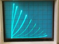
I have been reading the excellent thread by wrenchone in which he talks about Schade feedback. Out of curiosity I built the little IRFP240 example Schade circuit that consists of a 10K feedback resistor drain to gate with a 1K input resistor in series with the gate. I got almost exactly the same curves on my curve tracer that were pictured in the thread. I got to thinking that it is too bad that the input impedance is low ( equal to the input resistor I think), so I thought I would try a similar circuit with one of my C2M1000170D low capacitance SiCMosfets. Since the capacitance is about a factor of ten lower, I figured I could get away with increasing the resistor values by ten also. So I built up the new version and hooked it up to the tracer. I think the curves are very interesting. Not as linear as the 240 curves and quite different in shape. The settings for the photo were as follows:
5 V per division horizontal
100 mA per division vertical
1 V per step gate drive
50 ohm load limiter
I notice very characteristic of non-planar triode "lean to the right".
Normally I would have to sum 4 or more slightly different devices
and Schades to build a curve set that leans in that realistic way.
The lean comes from former members of the overall set in cutoff.
Those with highest Gm pinching themselves out of the equation.
A theory I once overheard from Smoking Amp, and ran with it.
We can learn from this something of the internal SICFET behavior.
I would now assume it is a large set of not entirely uniform cutoff.
Not saying this is bad or good, only interesting behavior. Taking
notes and jumping to conclusions.
I once built a realistic leaning SPICE model for 12AT7 of 10
slightly different perfect ^1.5 law subtriodes that individually
do not lean. Just to prove the point of what likely causes lean
in the first place. Perhaps what happened with your SICFET.
Last edited:
Hello kenpeter. Is it plausible to Schade a triode and/or a V-Fet; for more or less lean; good or bad?
Last edited:
Ive seen some of these SiC devices lately and wondered about them.
They all seemed to be UHT devices, with corresponding metal/ceramic packages, transistors and also op amps.
What are the benefits of such devices other than the high withstand temps? (they seem to be used for drill rig equipment)
They all seemed to be UHT devices, with corresponding metal/ceramic packages, transistors and also op amps.
What are the benefits of such devices other than the high withstand temps? (they seem to be used for drill rig equipment)
With a Schaded single device, I would expect parallel curves.
Its obvious from the posted curveset that a SICFET is neither
one device nor a set of perfectly matched subdevices.
You can make more lean by starting with a wildly varied set.
The only way to make less lean is for all members to match.
Those paths through a triode that have highest gains will cut
off earliest, and remove themselves from the set's behavior.
When approaching cutoff, the curve flattens more than one
might expect from Langmuir Child's law. Mu is reduced near
cutoff, and set theory explains why without resorting to any
exotic math cheats to fit an arbitrary curve.
Granted one pass with clever cheats is a lot more efficient
way to SPICE up some realistic curves than 4 to 10 parallel
simulations without cheats. But build a real circuit that will
faithfully compute Koren, I think not....
Now, don't go expecting perfectly parallel ^1.5 curves from
sand, as thats a vacuum thing. I think Si MOSFET may be ^2.
And don't get me lying about SICFETs, cause I don't know...
But the native power law is less and less relevant as it gets
squished by paths dropping out of set. A well spread set of
four can still blend to a good approximation of classic triode.
It was interesting the SICFET did this with a single device.
Last edited:
With a Schaded single device, I would expect parallel curves.
Its obvious from the posted curveset that a SICFET is neither
one device nor a set of perfectly matched subdevices.
You can make more lean by starting with a wildly varied set.
The only way to make less lean is for all members to match.
Those paths through a triode that have highest gains will cut
off earliest, and remove themselves from the set's behavior.
When approaching cutoff, the curve flattens more than one
might expect from Langmuir Child's law. Mu is reduced near
cutoff, and set theory explains why without resorting to any
exotic math cheats to fit an arbitrary curve.
Granted one pass with clever cheats is a lot more efficient
way to SPICE up some realistic curves than 4 to 10 parallel
simulations without cheats. But build a real circuit that will
faithfully compute Koren, I think not....
Now, don't go expecting perfectly parallel ^1.5 curves from
sand, as thats a vacuum thing. I think Si MOSFET may be ^2.
And don't get me lying about SICFETs, cause I don't know...
But the native power law is less and less relevant as it gets
squished by paths dropping out of set. A well spread set of
four can still blend to a good approximation of classic triode.
It was interesting the SICFET did this with a single device.
kenpeter
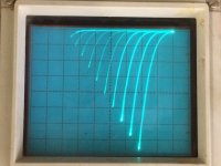
Thank you for the insights into the possible significance of the curve sets. It is more interesting to look at them now that I have a bit of appreciation for how unique they may be. Just to illustrate the difference between the Schade curves for the IRFP240 and the Cree devices in the same network topology, I will try to attach both below. The silicon MOSFET does have parallel curves. I had not thought of why that may be until you mentioned the effect cell uniformity may have on composite device curves. Very interesting. Also after this experiment of looking at network curve sets rather than just an active device alone, I am thinking of trying it on other combinations too.
Attachments
It looks real linear but I am not that knowledgeable on reading a curve. Someone correct me if I am wrong.
Here is the IRFP240 Schaded curve set
give us more info about that graph , and shade network you used
ideally , those lines need to be perfectly aligned , at angle of 45 deg.
(OK , I know it's matter of scaling )
damn
I almost dropped my monitor , while rotating in for last picture

Haha
Sorry Zen Mod!
Maybe someday I will learn how to get the pictures uploaded the right way...
I can't manage to get more than one per comment, and more often than not it is upside down! If there is a tutorial somewhere I would glad to know.
Worst thing is when it was hanging upside down like that all the electrons fell out!
- Home
- Amplifiers
- Pass Labs
- new SiC JFETs?