Lumba Ogir said:PMA,
to me the H configuration is inferior. What is the idea behind it?
How do you estimate correct resistor values and how do you make performance tuning?
In case you change gain resistor in H and Pi configuration, you do not change bias current. If you do this in T. you change bias current at the same moment.
I find correct values of resistors in MC simulation and then verify by prototyping. MC is a very powerfull tool, which shortens prototyping and optimization significantly.
halo
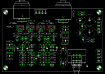
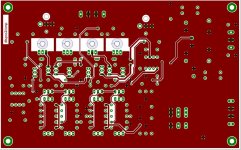
finally i have finished to construc the first dispre. with my own layout.

fisrt i test with my DX Vanilla.😀

I like the sound!
i use 50K pot, because only that value, i can get a GOOD pot. is the value make the pre-amp not stable?
why the pot should 5K or 10K?
tomorrow i will test it with my Symasym and Lynx3.0 too.
Thank's Pavel to share the Schematic.
La Ode
finally i have finished to construc the first dispre. with my own layout.

fisrt i test with my DX Vanilla.😀

I like the sound!
i use 50K pot, because only that value, i can get a GOOD pot. is the value make the pre-amp not stable?
why the pot should 5K or 10K?
tomorrow i will test it with my Symasym and Lynx3.0 too.
Thank's Pavel to share the Schematic.
La Ode
Stability would not be any issue, but you load it by 10k of R10 and R26:
http://web.telecom.cz/macura/dispre.png
http://web.telecom.cz/macura/dispre.png
Very nice Pavel, well done ...
especially that a 50K pot can be used, the output impedance is only a few ohms, low NFB, low THD, and of course all the other good features ... excellent, congrats ...
🙂
especially that a 50K pot can be used, the output impedance is only a few ohms, low NFB, low THD, and of course all the other good features ... excellent, congrats ...
🙂
Bonsai,
reading your posts has struck me that you are using devices meant for switching and other industrial applications, where linearity and other valuable parameters in audio are almost a nuisance. Several Japanese companies, in the first place Toshiba and Hitachi during decades have developed a large number of types directly for audio possessing deep knowledge in this field.
American and European manufacturers have never been interested in the small audio market.
I prefer Japanese stuff as it is way better in every aspect, superior chip design and manufacturing technology (both of equal importance).
So I simply don`t understand...
Bonsai,
these are not good sounding types (not when tweaked either), you could find some better without searching too long.I'm using 557/547. distortion is at 20Khz sine. I will tweak some more.
Yes. The produced PCB will be assembled and completely tested about mid June. Then 1st series (already sold out) will follow, and I guess that at the end of July the PCBs should be available.
A possible error in the design and pcb: Shouldn't Q4 and Q7 have emitter resistors? Now the output stage will run in class B or at least have very little bias. The output stage will also be very sensistive against temperature changes. I'll suggest 10-22 ohms and R11, R11 maybe 2.2 ohms.
No, you are wrong. The output stage runs in class A, at some 12mA. Also, the resistor values actually used have never been shown.
Anyway, thank you for your concern.
Anyway, thank you for your concern.
Hi,
based on that 12mA of output bias, I agree with Peranders that emitter resistors between 10r to 22r are required for Q4 & Q7.
I just calculated 14r for the output stage to achieve that bias.
What Vbe are necessary on Q4, 6, 7 & 8 to achieve 12mA of ClassA bias without using these extra emitter resistors?
Guys, I have a simulation, I have a working sample built that corresponds to simulation. You are just guessing.
Think about Vbe voltages and their dependence on Ic. No emitter resistors needed for my configuration and transistors.
Think about Vbe voltages and their dependence on Ic. No emitter resistors needed for my configuration and transistors.
What about the schematics in post 49?PMA said:No, you are wrong. The output stage runs in class A, at some 12mA. Also, the resistor values actually used have never been shown.
Anyway, thank you for your concern.
- Home
- Source & Line
- Analog Line Level
- New DISPRE preamp, successor to previous popular version

