Hi Pavel
Very Nice ...
Just to ask, you wouldn't happen to have 1 PCB available, would you?
If so, I would like one, thank you ...
🙂
Very Nice ...
Just to ask, you wouldn't happen to have 1 PCB available, would you?
If so, I would like one, thank you ...
🙂
Thanks to all for kind words.
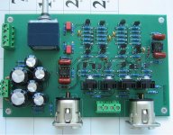
The final PCB with groundplane and RC supply filters for frontend resulted in considerable S/N improvement for lower frequencies. And substitution of 2N5551/2N5401 for BC547/BC557 resulted in lower distortion, and lower noise as well. The final circuit is as attached, PCBs will be available.
The final PCB with groundplane and RC supply filters for frontend resulted in considerable S/N improvement for lower frequencies. And substitution of 2N5551/2N5401 for BC547/BC557 resulted in lower distortion, and lower noise as well. The final circuit is as attached, PCBs will be available.
Attachments
Interesting that using BC547/557 resulted in lower distortion than for the 2N5551/2N5401 😕
Do you have an idea why you got this result ?
Do you have an idea why you got this result ?

Hello all,
I've seen some graph on the slovak board and this one are still more amazing.
A THD of 0,0003 % is something we can neglect indeed. Really good for small voltage swing and your measurement for higher voltage are really good against some other amplifier.
I've seen some graph on the slovak board and this one are still more amazing.
A THD of 0,0003 % is something we can neglect indeed. Really good for small voltage swing and your measurement for higher voltage are really good against some other amplifier.
Hi Max,
thank you. You know, my goal was not to get lowest THD from the preamp. In that case I would use opamp. But the opamp approach is what I want to avoid, I emphasize speed, no slew rate limitation = consistent transient response for all amplitudes, and low distortion even at 100kHz and 1MHz, for the reason to avoid RFI induced troubles.
thank you. You know, my goal was not to get lowest THD from the preamp. In that case I would use opamp. But the opamp approach is what I want to avoid, I emphasize speed, no slew rate limitation = consistent transient response for all amplitudes, and low distortion even at 100kHz and 1MHz, for the reason to avoid RFI induced troubles.
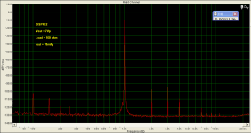
As you mentioned high amplitudes, I will show 7Vp into 100 ohm load, i.e. 70mAp output (not many preamps would probably work under these conditions). In this case, we can see crossover distortion. It is indicated by 7th harmonic (as John Curl properly stated), at level of some -110dB relative to fundamental. Also, multiples of 50Hz are seen, a result of one-way rectifier power supply residual, and underdimensioned trafo.
Attachments
PMA -
did you test if it was the ground plane or (and) the the RC supply filters for the frontend
that increased S/N?
regards,
Sigurd
did you test if it was the ground plane or (and) the the RC supply filters for the frontend
that increased S/N?
regards,
Sigurd
PMA said:Thanks to all for kind words.
The final PCB with groundplane and RC supply filters for frontend resulted in considerable S/N improvement for lower frequencies. And substitution of 2N5551/2N5401 for BC547/BC557 resulted in lower distortion, and lower noise as well. The final circuit is as attached, PCBs will be available.
PMA - I guess you mean generator+analyser, no?
Sigurd
Sigurd
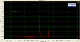
PMA said:Please compare to generator distortion itself:
PMA said:As you mentioned high amplitudes, I will show 7Vp into 100 ohm load, i.e. 70mAp output (not many preamps would probably work under these conditions). In this case, we can see crossover distortion. It is indicated by 7th harmonic (as John Curl properly stated), at level of some -110dB relative to fundamental. Also, multiples of 50Hz are seen, a result of one-way rectifier power supply residual, and underdimensioned trafo.
Hi Pavel
Have you in your possession a Sound Technology analyzer?
Fotios
the dispre just gets better and better.
But, why did you choose 2n in the first place? It's the last thing I would have done, but you must have had reasons.
Please explain.
But, why did you choose 2n in the first place? It's the last thing I would have done, but you must have had reasons.
Please explain.
Andrew, from the beginning it was planned with BC547/BC557. But, I did not have enough of BCs at the moment when I assembled the breadboard functional sample, so I used the 2Ns. The final PCB has been assembled with proper BCs now.
Sigurd Ruschkow said:PMA - I guess you mean generator+analyser, no?
Sigurd
It is mostly distortion of the generator. I had borrowed better generator in the past, and I measured much lower distortion limit of the soundcard.
fotios said:
Hi Pavel
Have you in your possession a Sound Technology analyzer?
Fotios
No. But I might have an access to AP2722 system, unfortunately not regularly.
I'm trying to learn and read about the new dispre but cannot find a schematic here with resistor values to sim in my software. Does one exist?
rob
rob
- Home
- Source & Line
- Analog Line Level
- New DISPRE preamp, successor to previous popular version