Those interested in PCB, please send me an e-mail. Regarding component values, I will send documentation with BOM and assembly instructions together with PCB, it is not to released right now here.
rob - you could use a simulator and try to get the amplfier working by yourself. It is a nice challenge 🙂
Get the input stage working, and then get on to the output stage.
Then, when you get the PCBs, you can compare what PMA uses against what you got.
A JFET input stage version would be nice to work on, too. Using 2SK170 / 2SJ74 matched. That is how I would do it.
Sigurd
Get the input stage working, and then get on to the output stage.
Then, when you get the PCBs, you can compare what PMA uses against what you got.
A JFET input stage version would be nice to work on, too. Using 2SK170 / 2SJ74 matched. That is how I would do it.
Sigurd
robmil said:I'm trying to learn and read about the new dispre but cannot find a schematic here with resistor values to sim in my software. Does one exist?
rob
fotios said:
Hi Pavel
Have you in your possession a Sound Technology analyzer?
Fotios
I ask you this because, in your posts 127, 128 and 131 in the pictures quoted it is obvious the logo of Sound Technology (S/T) in the upper right corner. So, i can suppose that these measurements are taken from a S.T. analyser.
Fotios
PMA said:But the opamp approach is what I want to avoid, I emphasize speed, no slew rate limitation = consistent transient response for all amplitudes
A slew rate limitation does not = an inconsistent transient response for different amplitudes.
Aline Nakashima 

An externally hosted image should be here but it was not working when we last tested it.
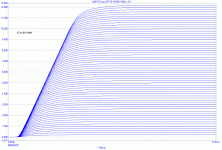
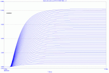
Glen, consistent for me means that step response with 10V amplitude is exactly same as 10 * 1V response. Not a case for slew rate limited circuits, as shown. No input RC aplicable. Even if yes, PIM remains. Sorry I will not argue more, being quite busy now.
Attachments
PMA said:Glen, consistent for me means that step response with 10V amplitude is exactly same as 10 * 1V response. Not a case for slew rate limited circuits, as shown. No input RC aplicable.
In post 2361 here:
http://www.diyaudio.com/forums/showthread.php?postid=1507034#post1507034
I already demonstrated that this claim is false.
Cheers,
Glen
I will reply to all who have sent me an e-mail with PCB request, hopefully tomorrow. Just trying to manage my time, please be patient 😉 . Thanks.
PMA said:You have demonstrated nothing. You would need 10x more resolution on time axis to demonstrate anything.
LOL!
If you say so.
Attached below is a plot of a 20kHz square wave output of 10V peak of an opamp that slews 40V/us against a 1V peak output magnified by 10.
How is this a degree of step response inconsistency that can have any bearing on the fidelity of an amplified audio signal?
How is this a degree of step response inconsistency that can have any bearing on the fidelity of an amplified audio signal?
Attachments
Hi Pavel
I showed a friend of mine your schematic and he had some nice words to say, so I thought that I would share them with you ...
🙂
I showed a friend of mine your schematic and he had some nice words to say, so I thought that I would share them with you ...
PMA does circumvent one typical problem (output loading) by inserting a diamond buffer between the output stage of the preamp and the load outside. Nevertheless, the other characteristics are fantastic. Such a pulse response is not found every day.
🙂
Thank you very much.
BTW, I have already found a while to reply to those who had sent me e-mails, sorry for the delay.
BTW, I have already found a while to reply to those who had sent me e-mails, sorry for the delay.
From our listening session on Saturday, June 14.
Speaker and some gear:
http://web.telecom.cz/macura/sess_speaker.jpg
On-site measurement of speakers:
http://web.telecom.cz/macura/sess_speakermeas.jpg
Upupa Epops (left), and me (right):
http://web.telecom.cz/macura/pma_upupa.jpg
Speaker and some gear:
http://web.telecom.cz/macura/sess_speaker.jpg
On-site measurement of speakers:
http://web.telecom.cz/macura/sess_speakermeas.jpg
Upupa Epops (left), and me (right):
http://web.telecom.cz/macura/pma_upupa.jpg
PMA - with only 10dB gain, do you really need to have the DC servo?
I sometimes can do without DC servo with up to 12 dB gain, but then I glue/couple the input JFETs together, and have a fairly constant amp temperature inside its box. DC offset is trimmed to <3mV and stays close to 3mV during the day/season.
Sigurd
I sometimes can do without DC servo with up to 12 dB gain, but then I glue/couple the input JFETs together, and have a fairly constant amp temperature inside its box. DC offset is trimmed to <3mV and stays close to 3mV during the day/season.
Sigurd
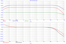
PMA said:For those who read in Bode plots:
The input stage does not behave much like standard LTP - remeber you do not know the resistor values, that are key factor to this preamp. Also, see small difference between Adiff and Acl - there is nothing to keep very low DC without servo. In case you afford DC offset like 100mV - 300mV, then you do not need the servo. I want the servo, and I see no sonic problem when it is applied.
- Home
- Source & Line
- Analog Line Level
- New DISPRE preamp, successor to previous popular version


