yes, informed guessing, so post some voltages/currents on the output section you have already revealed.
Hi PMA,
thanks for those currents.
I have no problem with you keeping the front end values to yourself.
I am only too glad that you have given as much as you have already.
thanks for those currents.
I have no problem with you keeping the front end values to yourself.
I am only too glad that you have given as much as you have already.
Andrew,
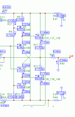
the component values may be released, but not earlier than the final PCB is assembled, tested and proven by listening tets. I am still not sure if I will release the values or include documentation for those who purchase the PCBs. Here in Prague I have just chosen the 2nd option, i.e. diy guys will get full documentation together with PCBs.
Regards,
Pavel
When I elaborated with my diamond buffer I got not so stable current when the emitter resistors had a big quot. It got very sensitive against temperature variations. You have 3.3/"0". I have tested 2.2/10 with good results. This resulted in approx 5 times the current at the output transistors compared to drivers. If it works you, it's actually better to have zero emitter resistance. You are not a fan of cascodes? I have cascoded emitter loads and I'll guess I'll got a "ynkro" lower distortion.PMA said:Not very informed, indeed. I am not disclosing more.
Notice that my diamond buffer was SMD so the pcb heated up parts also.
ynkro = less than little 😀
Compare this with the error correction guys where ultra low distortion is important 😀PMA said:Harmonic distortion was not the main goal. However, it is low enough not to be audible.
Still, I'll agree with you that sufficiently low distortion can be quite high but it is technically exciting to achieve extremely low distortion values.

I am not an armchair designer. I know that there are other important influences than THD, if THD is reasonable low. Do you care about THD well below 0.001%? 😉

pma:
impressive! thanks for sharing.
so you're doing a line preamp, also doing the RIAA preamp at the same time?
with a regular day job, too?
my only question is do you ever sleep?
😀
mlloyd1
impressive! thanks for sharing.
so you're doing a line preamp, also doing the RIAA preamp at the same time?
with a regular day job, too?
my only question is do you ever sleep?
😀
mlloyd1
PMA said:100kHz into 50 ohm, 200mV.
mlloyd1 said:
so you're doing a line preamp, also doing the RIAA preamp at the same time?
with a regular day job, too?
my only question is do you ever sleep?
😀
mlloyd1
Thanks 😉
Yes, you are quite right. I am well over 50, so I do not need to sleep that much 😀

Hallo, PMA.
Have You plan a headphone amplifier version(down to 32 Ohm load...) of Your circuit ?
With so good performances and cheep transistors type I think
it should be very interesting for a lot of people!
Thank You and compliments!
Semola
Have You plan a headphone amplifier version(down to 32 Ohm load...) of Your circuit ?
With so good performances and cheep transistors type I think
it should be very interesting for a lot of people!
Thank You and compliments!
Semola
Nice work!PMA said:

..but you did forget to write "ultra high performance" all over the board. That would avoid annoying a certain person.
Thanks,
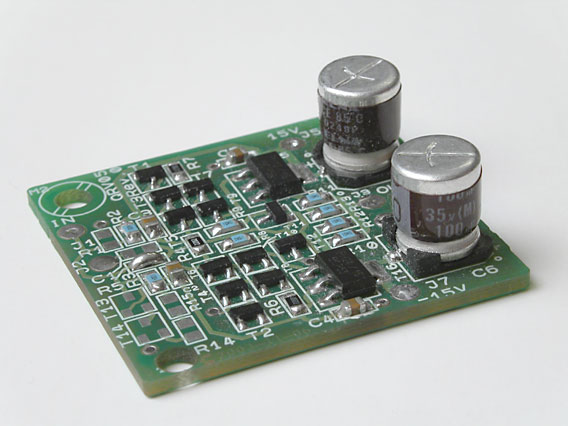
this preamp would easily drive the headphones. It has nice heatsinks, I will post a photo after it is completely assembled.
this preamp would easily drive the headphones. It has nice heatsinks, I will post a photo after it is completely assembled.
- Home
- Source & Line
- Analog Line Level
- New DISPRE preamp, successor to previous popular version