For power supply voltage 2 x 15V it is good to use a small heatsink for BD139/140, but not absolutely necessary. In case you used MJE15030/031, the bias current would increase (lower Vbe) and hetsinks became necessary.
Regarding BC546/7 in older version of Dispre, I tried both and did not hear any difference.
Regarding the new version, I am evaluating not only BCs, but 2N5551/2N5401 as well.
Regarding BC546/7 in older version of Dispre, I tried both and did not hear any difference.
Regarding the new version, I am evaluating not only BCs, but 2N5551/2N5401 as well.
PMA said:For power supply voltage 2 x 15V it is good to use a small heatsink for BD139/140, but not absolutely necessary. In case you used MJE15030/031, the bias current would increase (lower Vbe) and hetsinks became necessary.
Regarding BC546/7 in older version of Dispre, I tried both and did not hear any difference.
Regarding the new version, I am evaluating not only BCs, but 2N5551/2N5401 as well.
so, i can use 2sa1837 and 2sc4793 too for replace BD139/140?
i have already for those toshiba transistor.
I am not sure. Vbe of power transistors is crucial to get correct bias current. You need to measure voltage drop accross 2.7 ohm Re resistors to be sure.

Did you remove capacitor in the FB? It seems to me that there is no one on your board.
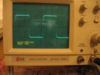
Curve on the oscilloscope is like a dream 🙂 🙂 🙂
Curve on the oscilloscope is like a dream 🙂 🙂 🙂
Right now, there is no FB capacitor. There is no capacitor in the signal path at all! There will be a capacitor of 2pF or 3pF on the finished product, just to feel safe and to get considerable phase margin. The output series resistor on the board, right now, is only 2.7 ohm.
I have some new results measured on the sample. Schematic of the sample is attached.
Tr(10%-90%) = 168ns, regardless amplitude.
Distortion in audio band is according to simulation. I have measured HF distortion by Rohde+Schwarz FSP7 spectrum analyzer. Results:
100kHz/1V/50 ohm:
2H under measurement limit
3H ... -73.94dB
1MHz/1V/50 ohm:
2H ... -63.44dB
3H ... -62.46dB
The load was 50 ohm.
Attachments


Nice design.
You can get better PSRR by disconnecting junction
r9/r15 from ground & replacing r27&r22 with diodes.
Ron
You can get better PSRR by disconnecting junction
r9/r15 from ground & replacing r27&r22 with diodes.
Ron
Very, very nice PMA. I also like 'stiff' output stages. Per my earlier question, will you feed this from a 50k volume pot?
Ron's suggestion is good BTW.
Also, with a diamond buffer, I have had good results by elavating the output transistor bases by 0.2V by inserting a BAT54 diode in series with the pre-driver emitters and taking the output transistor bases from the 'far' side of the diodes. This allows the output stage to run class A but with output s/circuit protection (from Iomax = 0.2V/Remmiter). A lot of diomond buffers use a current source load (yr Q4 and Q9). If you use the BAT54 trick you can take these out for virtually no degradation in performance. Just use a resistor from the rails - I set the pre-driver current for 2mA with 0V input.
Anyway, great result.
🙂
robo7 said:Nice design.
You can get better PSRR by disconnecting junction
r9/r15 from ground & replacing r27&r22 with diodes.
Ron
Thank you, you are right. The ground connection is made only in a sample, for final PCB it is disconnected. I will consider use of diodes.
Bonsai said:
Also, with a diamond buffer, I have had good results by elavating the output transistor bases by 0.2V by inserting a BAT54 diode in series with the pre-driver emitters and taking the output transistor bases from the 'far' side of the diodes. This allows the output stage to run class A but with output s/circuit protection (from Iomax = 0.2V/Remmiter). A lot of diomond buffers use a current source load (yr Q4 and Q9). If you use the BAT54 trick you can take these out for virtually no degradation in performance. Just use a resistor from the rails - I set the pre-driver current for 2mA with 0V input.
Anyway, great result.
🙂
Thanks for your suggestion, I will think it over.
PMA, I dont see resistor values for th efront end of your circuit.
Anyway, I took a shot at working out some values myself . . . . and can confirm th etopology gives excellent sim results. I got around .00018% at 2.5Vpk-pk distortion and circa 100nS rise and fall times.
Anyway, I took a shot at working out some values myself . . . . and can confirm th etopology gives excellent sim results. I got around .00018% at 2.5Vpk-pk distortion and circa 100nS rise and fall times.
Bonsai said:PMA, I dont see resistor values for th efront end of your circuit.
Anyway, I took a shot at working out some values myself . . . . and can confirm th etopology gives excellent sim results. I got around .00018% at 2.5Vpk-pk distortion and circa 100nS rise and fall times.
It may be even better (distortion), just a question of resistor values and devices (try with BC547/557).
I am not releasing the resistor values. I will probably only send it with PCBs or completed modules as a documentation.
I'm using 557/547. distortion is at 20Khz sine. I will tweak some more.
BTW, I tried a CFA front end and got 0.6ppm at 20Khz.
😉
BTW, I tried a CFA front end and got 0.6ppm at 20Khz.
😉
- Home
- Source & Line
- Analog Line Level
- New DISPRE preamp, successor to previous popular version